Water-gas replacement type underwater equipment auxiliary installation device and method

A technology for underwater equipment and installation devices, which is applied to underwater operation equipment, transportation and packaging, ships, etc. It can solve the problems of high cost, inconvenient transportation of underwater equipment, and large bearing capacity of installation cables, and achieve low cost and weather protection. The effect of low condition requirements and not easy to be affected by bad weather

Active Publication Date: 2016-07-20
无锡市弘泰检测科技有限公司
View PDF7 Cites 9 Cited by
  • Summary
  • Abstract
  • Description
  • Claims
  • Application Information

AI Technical Summary

Problems solved by technology

[0004] In order to overcome the defects of the prior art, the present invention provides a water-air displacement auxiliary installation device and installation method for underwater equipment. The main body with a ballast tank is used to offset the buoyancy of the underwater equipment, and the device can be used to realize the installation of underwater equipment. Wet tow transportation and non-floating weight installation of underwater equipment to solve the problems of conventional underwater equipment installation technology, such as inconvenient transportation of underwater equipment, excessive bearing capacity of installation cables, and high cost

Method used


Image

  • Water-gas replacement type underwater equipment auxiliary installation device and method
  • Water-gas replacement type underwater equipment auxiliary installation device and method
  • Water-gas replacement type underwater equipment auxiliary installation device and method

Examples


Embodiment Construction

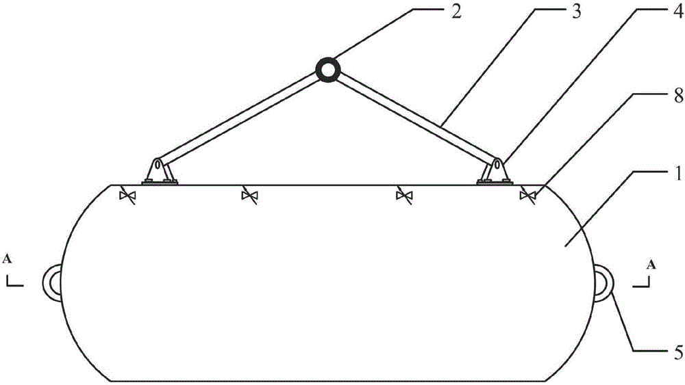
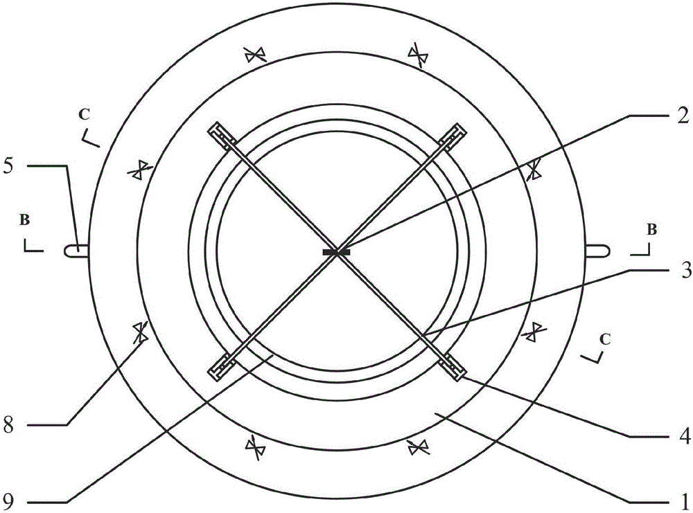
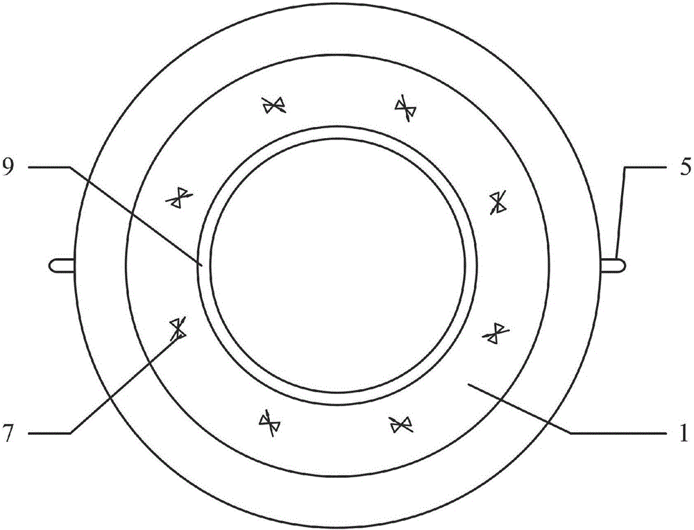
[0034] like figure 1 , figure 2 , image 3 , Figure 4 , Figure 5 , Image 6 As shown, the water-gas replacement underwater auxiliary installation device includes: main body 1, hinge support 4, bracket 3, bracket lifting ring 11, lifting lug 5, ballast tank 6, water inlet valve 7, exhaust valve 8, rubber Washer 9.

[0035] The main body 1 is drum-shaped as a whole, and the outer wall 32 of the main body is smooth and streamlined; the inner wall 31 of the main body is cylindrical, and the top is chamfered; the main body 1 is made of steel and can withstand deep water pressure; the top surface of the main body 1 is provided with four hinge supports 4. The four hinge supports 4 are evenly distributed along the circumference, each hinge support 4 is connected with a bracket 3 , and the tops of all the supports 3 are connected with the bracket rings 2 , which are used to connect the load-bearing hooks 33 .

[0036] The outer wall 32 of the main body 1 is provided with two l...


PUM


Abstract

The invention belongs to the technical field of ocean engineering and particularly relates to a water-gas replacement type underwater equipment auxiliary installation device and method. The water-gas replacement type underwater equipment auxiliary installation device comprises a main body, hinged supports, brackets, a bracket lifting ring, lifting lugs, ballast tanks, water inlet valves and exhaust valves. The water-gas replacement type underwater equipment auxiliary installation device is characterized in that the four hinged supports are arranged on the top surface of the main body and uniformly distributed in the circumferential direction; one bracket is connected to each hinged support; the top ends of all the brackets are all connected with the bracket lifting ring; the eight same ballast tanks are uniformly distributed in the main body and independent from one another; and the bottom of each ballast tank is provided with one water inlet valve, and the top of each ballast tank is provided with one exhaust valve. According to the water-gas replacement type underwater equipment auxiliary installation device and method, the tensile force borne by installation cables in the installation process is small, the main body of the auxiliary installation device is made of steel, the deep water pressure can be borne, and the cost is low, so that the auxiliary installation device is suitable for deep water installation; and no large-area deck ships needs to be employed to transport underwater equipment, and the underwater equipment can be dragged to the installation position at a port by a transport ship in a wet mode.

Description

technical field [0001] The invention belongs to the technical field of marine engineering, and in particular relates to an auxiliary installation device and an installation method of a water-vapor replacement type underwater equipment. Background technique [0002] The installation of underwater equipment is an important part of marine engineering. Foreign countries tend to mature in the field of underwater equipment installation technology, and the methods used include pulley installation method, hem method, pencil buoy method, etc. The above methods usually have relatively high requirements on the force-bearing capacity of the installation rod or installation cable, and require a large-area deck carrier to transport underwater equipment, which is expensive and easily affected by bad weather. Domestically, the development of underwater installation technology is limited, and the installation depth is relatively shallow. Most underwater installation projects can only rely o...

Claims


Application Information

Patent Timeline
Patent Type & Authority Applications(China)
IPC IPC(8): B63C11/52B66C13/04
CPCB63C11/52B66C13/04
Inventor 曹宇光甄莹张士华史永晋李森胡雪扬贺娅娅聂文俊李云鹏辛露
Owner 无锡市弘泰检测科技有限公司
Why Eureka
Try Eureka