A cylindrical wood burr grinding device
A cylindrical wood technology, applied in the field of cylindrical wood burr grinding devices, can solve the problems of uneven manual grinding and unsafety, and achieve the effect of enhancing the grinding effect and reducing the workload
- Summary
- Abstract
- Description
- Claims
- Application Information
AI Technical Summary
Problems solved by technology
Method used
Image
Examples
Embodiment 1
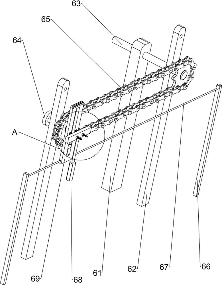
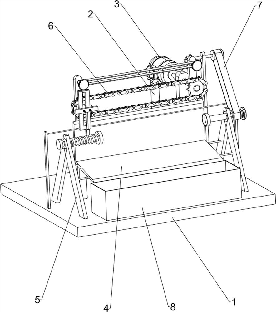
[0024] A cylindrical wood burr grinding device, such as figure 1 As shown, it includes a base 1, a support table 2, a motor 3, a receiving plate 4, a clamping mechanism 5 and a scraping mechanism 6, a support table 2 is provided on the rear side of the base 1, a motor 3 is installed on the top of the support table 2, and the base 1 The upper front side is provided with a clamping mechanism 5 , the middle of the base 1 is provided with a scraping mechanism 6 , the scraping mechanism 6 is connected with the motor 3 , and a receiving plate 4 is connected between the clamping mechanism 5 and the scraping mechanism 6 .
[0025] When people need to remove the burrs on the cylindrical wood, this grinding device can be used. First, people clamp the two ends of a cylindrical wood to be polished between the clamping mechanisms 5, and then start the motor 3, and the output of the motor 3 The rotation of the shaft drives the scraping mechanism 6 to operate, so that the grinding member on ...
Embodiment 2
[0027] On the basis of Example 1, as figure 2 , image 3 and Figure 4 As shown, the clamping mechanism 5 includes a support frame 51, a first rotating shaft 52, a rotating drum 53 and a first spring 54, and the left and right sides of the upper front of the base 1 are provided with support frames 51. A rotating drum 53 is provided, the upper part of the support frame 51 on the right side and the inside of the rotating drum 53 are rotatably provided with a first rotating shaft 52, the first rotating shaft 52 on the left side is slidably connected with the rotating drum 53, and the first rotating shaft 52 on the left side is slidably connected to the rotating drum 53. A first spring 54 is wound around the rotating shaft 52 , and the left end of the first spring 54 is connected to the drum 53 .
[0028] People clamp the two ends of the cylindrical wood to be polished between the first rotating shafts 52, the length of the wood is longer than the initial distance between the t...
Embodiment 3
[0032] On the basis of Example 2, as figure 1 and Figure 5 As shown, a rotating mechanism 7 is also included, and a rotating mechanism 7 is provided on the right side of the upper front part of the base 1. The rotating mechanism 7 is connected with the first rotating shaft 52 and the second supporting column 62, and the rotating mechanism 7 includes a third supporting column 71. , rotating rod 72, bevel gear set 73, first belt drive set 74, second belt drive set 75 and one-way gear 76, a third support column 71 is provided on the right side of the upper rear of the base 1, and the upper part of the third support column 71 The rotating rod 72 is provided with a rotating rod 72 , and the upper part of the second support column 62 is rotatably provided with a fifth rotating shaft 77 . The right side and the right side of the first rotating shaft 52 are drive-connected with a first belt drive group 74 on the right side, and the front sides of the two fifth rotating shafts 77 are...
PUM
 Abstract
Description
Claims
Application Information
 - R&D Engineer
- R&D Manager
- IP Professional
- Industry Leading Data Capabilities
- Powerful AI technology
- Patent DNA Extraction
Browse by: Latest US Patents, China's latest patents, Technical Efficacy Thesaurus, Application Domain, Technology Topic, Popular Technical Reports.
© 2024 PatSnap. All rights reserved.Legal|Privacy policy|Modern Slavery Act Transparency Statement|Sitemap|About US| Contact US: help@patsnap.com


