Full-automatic adjustable fixture for flywheel casing of new energy automobile and machining technological process

A new energy vehicle, flywheel housing technology, applied in metal processing equipment, metal processing mechanical parts, clamping and other directions, can solve problems such as being unable to meet large-scale assembly line production, consuming a lot of manpower, and unable to ensure smooth and effective processing.

Active Publication Date: 2021-01-01
杭州萧山汽车滤清器有限公司
View PDF8 Cites 2 Cited by
  • Summary
  • Abstract
  • Description
  • Claims
  • Application Information

AI Technical Summary

Problems solved by technology

Since the turning and milling of the flywheel housing needs to be performed on multiple surfaces, holes, grooves, chamfers, etc., multiple machine tools are required for assembly line work, so a lot of manpower is required in the fixture installation process of the flywheel housing, and th

Method used


Image

  • Full-automatic adjustable fixture for flywheel casing of new energy automobile and machining technological process
  • Full-automatic adjustable fixture for flywheel casing of new energy automobile and machining technological process
  • Full-automatic adjustable fixture for flywheel casing of new energy automobile and machining technological process

Examples


Embodiment 1

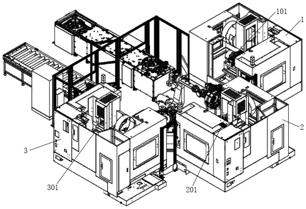
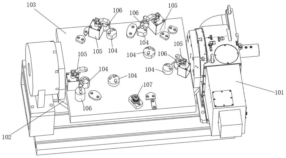
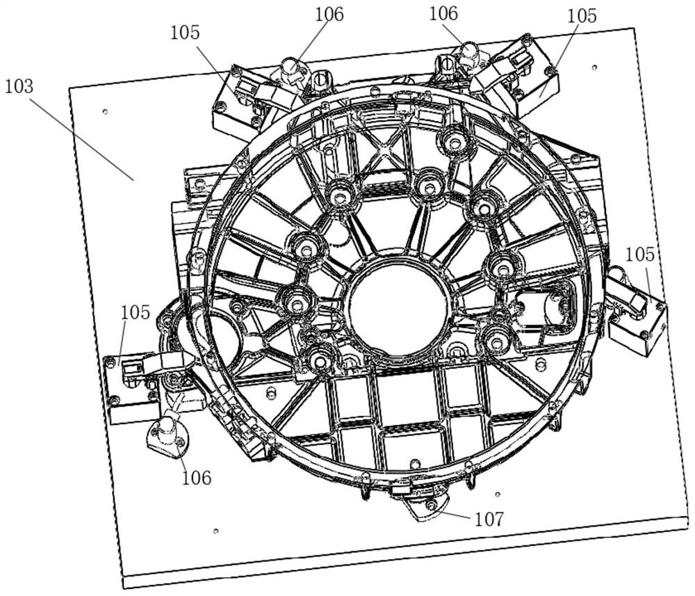
[0081] Embodiment 1: the fully automatic processing production line of the flywheel housing for new energy vehicles, such as figure 1 As shown, it includes the first processing station 101 arranged on the first turning-milling machine tool 1, the second processing station 201 arranged on the second turning-milling machine tool 2 and the third processing station arranged on the third turning-milling machine tool 3 Station 301, such as figure 2 and image 3 As shown, the first processing station 101 includes a first turntable 102 connected to the turntable at both ends, the first turntable 102 is provided with a first fixture panel 103, and the outer surface of the flywheel housing faces the first fixture panel 103. ; The surface of the first fixture panel 103 is provided with 6 first positioning pins 104, 4 first pressing members 105, 4 first air nozzles 106 and 1 first adjusting strut 107; One positioning pin 104 is respectively located at the four corners of the first fixt...

Embodiment 2

[0084] Embodiment 2: Utilize the fully automatic adjustable fixture for the flywheel housing of the new energy vehicle in Embodiment 1 to process the flywheel housing. The process is to place the unprocessed flywheel housing in the first processing station 101 of the first turning and milling machine tool 1 Carry out milling inner circle and flange surface, drilling and tapping, and countersinking on the second machining station 201 of the second turning and milling machine tool 2, and then carry out countersinking, drilling and tapping threaded holes, milling planes and drilling and tapping on the second processing station 201 of the second turning and milling machine tool Finally, on the third processing station 301 of the third turning and milling machine tool 3, fine milling of the joint surface, boring and drilling and tapping of the threaded holes is carried out, and the processing of the flywheel housing is completed after the three turning and milling operations are comp...


PUM


Abstract

The invention discloses a full-automatic adjustable fixture for a flywheel casing of a new energy automobile and a machining technological process. According to the process, the unmachined flywheel casing is subjected to inner circle and flange surface milling, drilling and tapping and spot facing on a first machining station of a first turning and milling machine tool, then is subjected to spot facing, threaded hole drilling and tapping, plane milling and threaded hole drilling and tapping on a second machining station of a second turning and milling machine tool, and finally is subjected tojunction surface finish-milling, boring and threaded hole drilling and tapping on a third machining station of a third turning and milling machine tool, and machining of the flywheel casing is completed after the three times of turning and milling are finished. Through the fixture, the flywheel casing can be clamped conveniently, the stability is good, the turning and milling precision is guaranteed, and the production efficiency is improved.

Description

technical field [0001] The invention relates to the technical field of automobiles, in particular to a fully automatic adjustable clamp for a flywheel housing of a new energy automobile and a processing flow. Background technique [0002] New energy vehicles refer to the use of unconventional vehicle fuels as power sources (or the use of conventional vehicle fuels, the use of new vehicle power devices), integrated vehicle power control and advanced technology in driving, the formation of advanced technical principles, with Automobiles with new technology and new structure. The hybrid vehicle in the new energy vehicle still has an engine. The flywheel housing is an important connecting part connecting the engine block and the gearbox. It is one of the parts of the engine. The flywheel housing is installed on the outside of the engine flywheel for the cover The flywheel acts as a safety protection. Since the turning and milling of the flywheel housing needs to be performed o...

Claims


Application Information

Patent Timeline
IPC IPC(8): B23Q3/06B23Q11/00B23P15/00
CPCB23P15/00B23Q3/06B23Q3/062B23Q11/0042
Inventor 韩华忠
Owner 杭州萧山汽车滤清器有限公司
Why Eureka
Try Eureka