Construction method of temporary supports of beam slab post-cast strip

A temporary support and construction method technology, which is applied to the preparation of formwork/formwork/work frame, pillars, and building components on site, and can solve the problem of not being able to adapt to post-cast belt support, top plate post-cast belt and bottom plate post-cast belt Issues such as insufficient fixation

Active Publication Date: 2021-09-10
CHINA METALLURGICAL CONSTR ENG GRP
View PDF17 Cites 3 Cited by
  • Summary
  • Abstract
  • Description
  • Claims
  • Application Information

AI Technical Summary

Problems solved by technology

However, the above-mentioned casing columns have the same height and cannot be adapted to the support of post-cast belts of buildings with different storey heights.
At the same time, after the casing string is installed, the fixation with the post-cast belt of the top plate and the post-cast belt of the bottom plate is not stable enough

Method used


Image

  • Construction method of temporary supports of beam slab post-cast strip
  • Construction method of temporary supports of beam slab post-cast strip
  • Construction method of temporary supports of beam slab post-cast strip

Examples


Embodiment

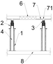
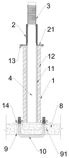
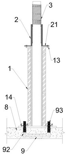
[0024]The method of construction with the temporary support after the casting slab according to this embodiment, comprising the steps of: S1, back strip 6 according to the design requirements, the profile of the temporary support after the rendering apparatus with pouring, the pouring belt along the temporary support means pouring belt 3 disposed longitudinal direction of the pitch, with cast slab formwork system 3 and located at the rear sides; back strip of the temporary support means comprises a support cylinder oriented by the lower set 1, the connecting tube 2 and the adjustment cylinder 3 the support tube 1 is a central steel support cylinder has a circular or rectangular through hole, the installation consists of a left and a right template from the template; the cartridge 2 is detachably connected to a support mounted on the cylinder 1, the adjustment cylinder 3 cartridge connecting sleeve 2, and is vertically movable and is positioned in the height direction of the connec...


PUM


Abstract

The invention discloses a construction method of temporary supports of a beam slab post-cast strip. The construction method comprises the following steps that according to the design requirements of the post-cast strip, a distribution diagram of temporary supporting devices of the post-cast strip is drawn; each temporary supporting device of the post-cast strip comprises a supporting cylinder, a connecting cylinder and an adjusting cylinder, wherein the middle of the supporting cylinder, the middle of the connecting cylinder and the middle of the adjusting cylinder are communicated, and a concrete pouring channel is formed after the middle of the supporting cylinder, the middle of the connecting cylinder and the middle of the adjusting cylinder are communicated; the multiple temporary supporting devices of the post-cast strip are installed and fixed to a beam slab of a bottom floor according to the distribution diagram of the temporary supporting devices of the post-cast strip, pouring openings are formed in bottom formworks of the beam slabs of the floors on the temporary supporting devices of the post-cast strip, and the pouring openings correspond to the concrete pouring channels of the temporary supporting devices of the post-cast strip one to one and are communicated with the concrete pouring channels of the temporary supporting devices of the post-cast strip; and concrete is poured into the formworks of the beam slabs of the floors, and after the concrete of the beam slabs of the floors reaches the formwork removal strength, the concrete in the temporary supporting devices of the post-cast strip forms temporary supporting columns of the post-cast strip.

Description

Technical field [0001] The present invention relates to a pouring strip of the method, particularly relates to a construction method of pouring the latter with the temporary support slab. Background technique [0002] It refers back strip unevenness, the uneven settlement construction for preventing situ reinforced concrete structures due to temperature changes, their construction requires shrinkage or harmful cracks may be generated, according to the design or construction specifications, the beam plate ( foundation slab), leaving in the corresponding position in the wall with concrete. [0003] After pouring band construction is common practice in the pouring of the rear and a separate supporting frame Pin Full disposed on two sides, after a predetermined time, and then after completion of the work of pouring pouring belt, after removal of the support frame member. For different types of water (e.g., stretching, settling, etc.) after the casting construction which requires diff...

Claims


Application Information

Patent Timeline
Patent Type & Authority Applications(China)
IPC IPC(8): E04G11/48E04G25/00E04G25/06
CPCE04G11/48E04G11/483E04G25/00E04G25/065E04G2025/006E04G2025/003
Inventor 范绍杰杨洋邱长林
Owner CHINA METALLURGICAL CONSTR ENG GRP
Why Eureka
Try Eureka