
EGR mixer capable of improving mixing uniformity

A mixing uniformity and mixer technology, which is applied in the field of EGR mixers for improving mixing uniformity, can solve the problems of pressure rise, affecting the exhaust gas flow and mixing uniformity of the EGR system, and achieve the effect of improving mixing uniformity.

Pending Publication Date: 2020-12-25
GUANGXI YUCHAI MASCH CO LTD
View PDF1 Cites 0 Cited by
  • Summary
  • Abstract
  • Description
  • Claims
  • Application Information

AI Technical Summary

Problems solved by technology

[0003] In the prior art, Chinese patent CN201320535712.4 discloses an EGR mixer for an exhaust gas recirculation diesel engine, including a mixer cavity and a mixer, one end of the mixer cavity is a natural air inlet, and the mixer cavity The other end of the mixer is the gas mixture outlet, and the mixer is fixed after passing through the side wall of the inner chamber of the mixer. The mixer hole is an array of holes distributed obliquely. Its disadvantage is that the holes are opened in the entire circumference of the mixer. Because the pressure of the natural air is higher than the exhaust gas pressure in the mixer tube, the natural air is poured into the EGR tube along the side hole of the mixer. The pressure inside the mixer pipe increases, and the flow of exhaust gas to the intake pipe is blocked, which affects the exhaust gas flow and mixing uniformity of the entire EGR system

Method used


Image

  • EGR mixer capable of improving mixing uniformity
  • EGR mixer capable of improving mixing uniformity
  • EGR mixer capable of improving mixing uniformity

Examples


Embodiment Construction

[0020] The present invention will be further described below in conjunction with the specific embodiments in the accompanying drawings.

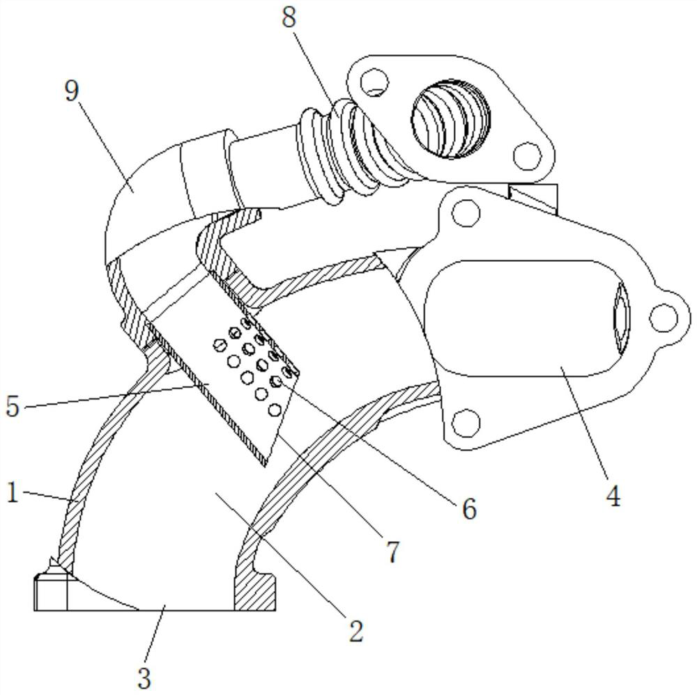
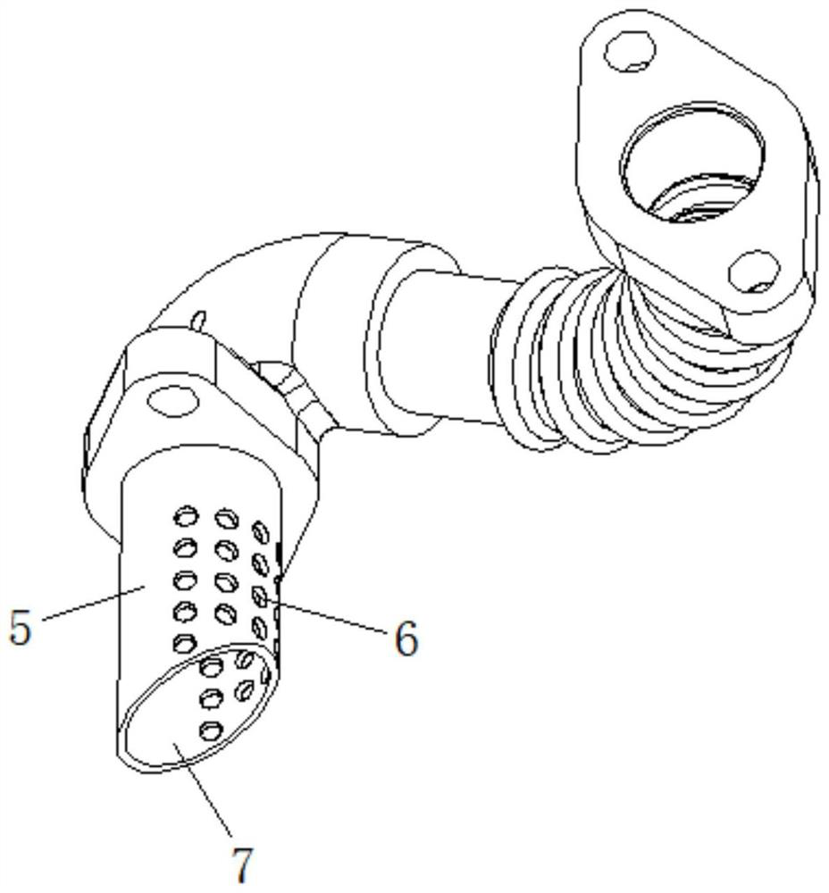
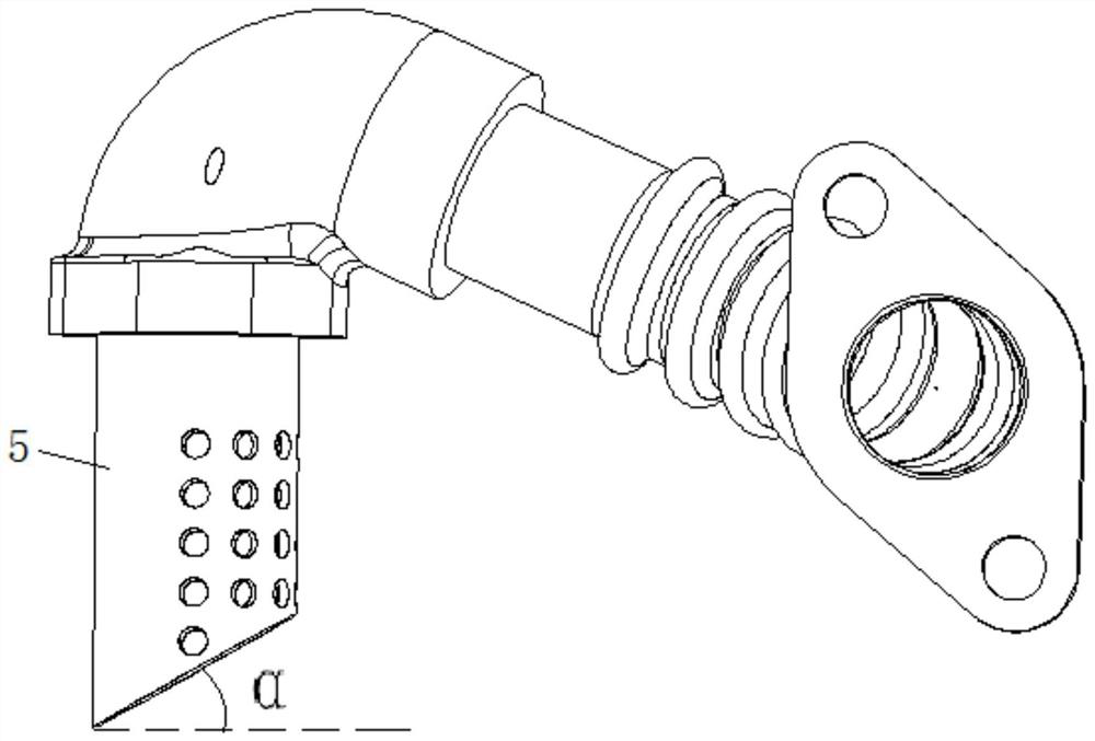
[0021] refer to Figure 1-3 , an EGR mixer for improving mixing uniformity, comprising a mixer body 1, a mixing chamber 2 is arranged in the mixer body 1, an air inlet 3 is arranged at one end of the mixing chamber 2, and a mixed gas outlet 4 is arranged at the other end . The EGR mixer also includes an EGR intake pipe 5 passing through the mixer body 1 and extending into the mixing chamber 2. The side of the EGR intake pipe 5 facing the mixed gas outlet 4 is provided with a plurality of uniformly arranged ventilation holes 6. The EGR intake pipe The bottom of 5 is provided with the oblique cut 7 facing the mixed gas outlet 4. Since the oblique cut 7 faces away from the high-pressure air inlet 3, a low-pressure area will be formed, which will help the exhaust gas to flow into the mixing chamber 2, and the vent hole 6 will also form a low-p...


PUM


Abstract

The invention discloses an EGR mixer capable of improving mixing uniformity, relates to the technical field of EGR mixers, and mainly solves the technical problem that natural air can flow back into an EGR pipe. The EGR mixer comprises a mixer body, a mixing cavity is formed in the mixer body, an air inlet is formed in one end of the mixing cavity, and a mixed gas outlet is formed in the other endof the mixing cavity. The EGR mixer further comprises an EGR air inlet pipe penetrating through the mixer body and extending into the mixing cavity, a plurality of evenly-arranged vent holes are formed in the side, facing the mixed gas outlet, of the EGR air inlet pipe, and an oblique notch facing the mixed gas outlet is formed in the bottom of the EGR air inlet pipe. The vent holes and the oblique notch are formed in the side, facing the mixed gas outlet, of the EGR air inlet pipe, a low-pressure area can be formed due to the fact that the vent holes and the oblique notch are back onto the high-pressure air inlet, waste gas can flow into the mixing cavity advantageously, natural air is prevented from flowing back into the EGR air inlet pipe, and then the mixing uniformity is improved.

Description

technical field [0001] The invention relates to the technical field of EGR mixers, more specifically, it relates to an EGR mixer for improving mixing uniformity. Background technique [0002] Exhaust gas recirculation (EGR, Exhaust Gas Recirculation) is an effective measure to reduce the generation of NOx gas in the engine cylinder. Its working principle is: a part of the exhaust gas of the engine is cooled and then sent back to the engine cylinder to participate in the combustion process. The gas composition in the combustion chamber comes from two parts, one part is the fresh air cooled by the intercooler, and the other part is the exhaust gas taken from the exhaust manifold and cooled by the EGR cooler. The function of the EGR mixer is to mix the two parts of the gas evenly, so as to avoid the problem that the gas composition in each cylinder is different due to uneven mixing, which affects the combustion of each cylinder. How to design the structure of the EGR mixer, a...

Claims


Application Information

Patent Timeline
Patent Type & Authority Applications(China)
IPC IPC(8): F02M26/19
CPCF02M26/19
Inventor 余超杨仕明王冲有
Owner GUANGXI YUCHAI MASCH CO LTD
Learn More