
Diffusion welding method utilizing material linear expansion coefficient difference

A linear expansion coefficient, diffusion welding technology, applied in welding equipment, non-electric welding equipment, metal processing equipment and other directions, can solve the problem of high requirements for auxiliary equipment

Inactive Publication Date: 2020-12-25
CHANGDE XIANGYU EQUIP MFG
View PDF6 Cites 0 Cited by
  • Summary
  • Abstract
  • Description
  • Claims
  • Application Information

AI Technical Summary

Problems solved by technology

[0005] The invention provides a diffusion welding method utilizing the difference in linear expansion coefficient of materials, aiming to solve the problem that the existing vacuum diffusion welding technology has high requirements for auxiliary equipment

Method used


Image

  • Diffusion welding method utilizing material linear expansion coefficient difference
  • Diffusion welding method utilizing material linear expansion coefficient difference
  • Diffusion welding method utilizing material linear expansion coefficient difference

Examples


Embodiment 1

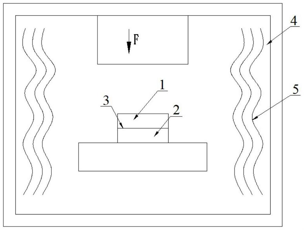
[0029] A diffusion welding method using a difference in the coefficient of linear expansion of materials provided by an embodiment of the present invention includes:

[0030] The first weldment and the second weldment made of 06Cr19Ni10 and the sheath made of SiC composite material are surface-treated to make the roughness ≤ 1.6μm and cylindricity ≤ 0.03mm, and then degrease and clean them to Material metal color and blow dry, SiC composite material is a composite material of silicon carbide and silicon.

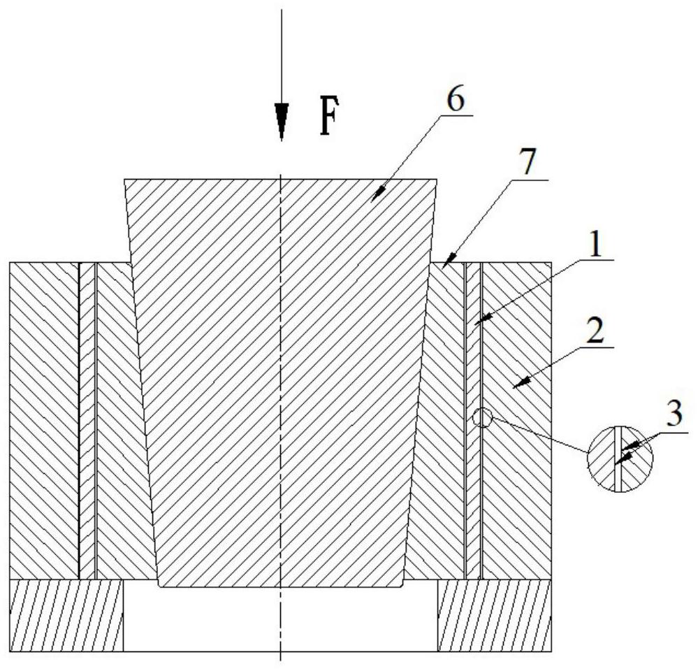
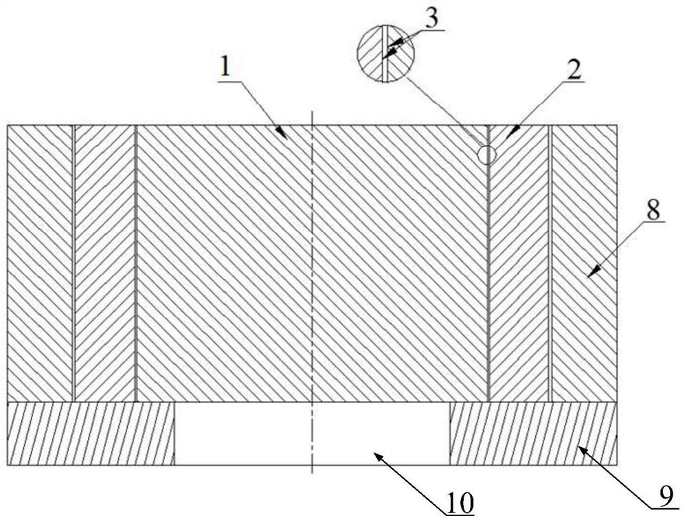
[0031] Put the first weldment and the second weldment to be welded into the sheath to form the first assembly, the second weldment is set with the first weldment, the sheath is set with the second weldment, the first weldment and the second weldment The gap between the weldments is 0.08mm, and the gap between the sheath and the second weldment is 0.15mm.

[0032] Place the first assembly on the backing tooling to form the second assembly, place the second assembly in a vacu...

Embodiment 2

[0036] A diffusion welding method using a difference in the coefficient of linear expansion of materials provided by an embodiment of the present invention includes:

[0037] The first weldment and the second weldment made of 6061 aluminum alloy and the sheath made of TC4 titanium alloy are surface treated to make the roughness ≤ 1.6μm and cylindricity ≤ 0.03mm, and then degrease and Wash to the metallic color of the material and blow dry.

[0038]Put the first weldment and the second weldment to be welded into the sheath to form the first assembly, the second weldment is set with the first weldment, the sheath is set with the second weldment, the first weldment and the second weldment The gap between the weldments is 0.05mm, and the gap between the sheath and the second weldment is 0.08mm.

[0039] Place the first assembly on the backing tooling to form the second assembly, place the second assembly in a vacuum furnace, and evacuate the vacuum furnace to below 9E-3Pa, accord...


PUM

PropertyMeasurementUnit
porosityaaaaaaaaaa
surface roughnessaaaaaaaaaa
Cylindricityaaaaaaaaaa

Abstract

The invention belongs to the technical field of welding, and provides a diffusion welding method utilizing a material linear expansion coefficient difference. The method is used for welding rotary parts. Weldments to be welded are sleeved with each other and then loaded into a sheath, certain gaps are reserved between the weldments to be welded and between a part and the sheath, and the linear expansion coefficient of the sheath is smaller than the linear expansion coefficients of the weldments. According to the arrangement, in the process of diffusion welding in a vacuum high-temperature environment, the weldments are heated to expand, the expansion degree of the sheath is smaller than that of the weldments, and the gap between the sheath and the weldments on the outer layer is graduallyreduced in the temperature rising process until the sheath hoops the weldments; and the sheath generates extrusion force on the weldments to be welded, and finally diffusion welding is achieved between the weldments to be welded. The requirement for diffusion welding auxiliary equipment is low, a pressure head does not need to be used for applying pressure, welding can be completed in vacuum heattreatment equipment, and tools and machining cost needed by welding can be effectively saved.

Description

technical field [0001] The invention belongs to the field of welding technology, in particular to a diffusion welding method utilizing the difference in linear expansion coefficient of materials. Background technique [0002] Vacuum diffusion welding technology is to place the parts to be welded in a vacuum furnace or a vacuum environment to give a certain temperature and pressure, so that the surfaces to be welded are in contact with each other, and under the action of pressure, the physical contact of the surfaces to be connected is enlarged through microscopic plastic deformation, so that the combination It is an advanced welding method in which the materials undergo inter-diffusion between atoms for a certain period of time to form a reliable overall connection while undergoing micro-plastic deformation and creep. Pressure is a necessary condition for the realization of diffusion welding. The welding surface of the parts to be welded is brought into a state of extrusion ...

Claims


Application Information

Patent Timeline
Patent Type & Authority Applications(China)
IPC IPC(8): B23K20/00B23K20/14
CPCB23K20/001B23K20/14
Inventor 高友价胡俊全书浩王昌国
Owner CHANGDE XIANGYU EQUIP MFG
Learn More