
Efficient gas pressure reducing device

A decompression device, gas technology, applied in the direction of the valve device, valve operation/release device, valve details, etc., can solve the problems of long control process, difficult modeling, complex force change, etc. The effect of pressure and efficiency improvement

Active Publication Date: 2020-12-22
泰安福星汽车配件有限公司 +1
View PDF14 Cites 0 Cited by
  • Summary
  • Abstract
  • Description
  • Claims
  • Application Information

AI Technical Summary

Problems solved by technology

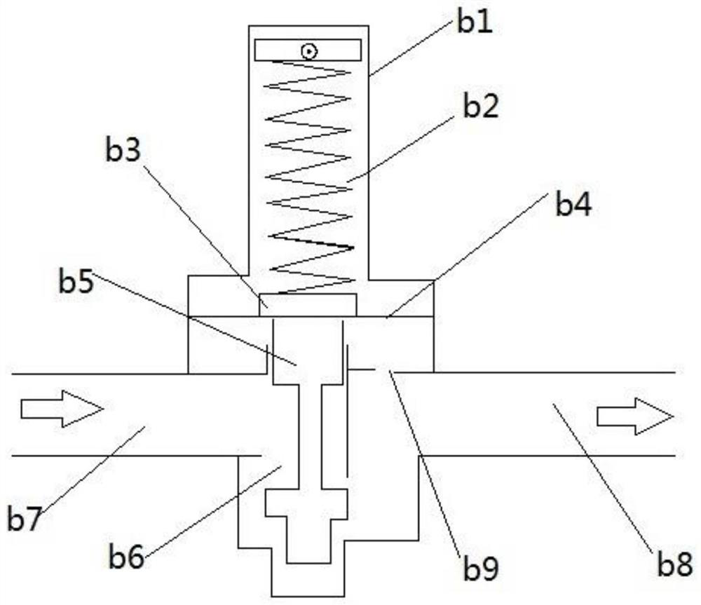
However, in fact, the above-mentioned control process is relatively long, mainly because the elastic force of the spring is not a constant force. Therefore, because the elastic force of the spring cannot fully guarantee the constant force state during use, the decompression process is relatively time-consuming. In addition, the control of the decompression amount from the high-pressure pipeline to the low-pressure pipeline in the above process is actually done by The downward spring force of spring b2 and the gas pressure are jointly determined, and neither force can be too large. This actually requires extremely high standards for the formulation of spring b2. In fact, it is difficult to achieve accurate preparation of spring b2 in traditional production, that is, It is difficult to precisely control the decompression from the high-pressure pipeline to the low-pressure pipeline. In order to improve the control of the decompression from the high-pressure pipeline to the low-pressure pipeline, in the traditional technology, it is necessary to improve and explore step by step through a large number of use or experimental data statistics. In fact, it is also because The elastic force of the spring is not a single constant force in use. Its own force changes are complex and difficult to model. It is also difficult to achieve precise theoretical control in the research on its use. In use, users often rely on high-pressure pipelines and low-pressure pipelines. The actual pressure count value to determine the amount of decompression from the high pressure pipe to the low pressure pipe, and then adjust the spring compression degree (actually adjust the spring force when the spring is balanced with the gas pressure), until the decompression amount from the high pressure pipe to the low pressure pipe is satisfactory The numerical value may be within a satisfactory numerical range. Here we can find that in fact, this kind of operation process is relatively complicated. Even some manufacturers may use a large amount of statistical data as a basis to mark the corresponding scale line in production. Regulation provides a reference, however, in the process of actual use, the stiffness coefficient of the spring will also change significantly due to the use time, and the spring and the pipe wall b1 in contact with each other will change due to the generation of metal oxides or corrosion over time Friction makes the decompression control very imprecise, and the control process is also very inefficient

Method used


Image

  • Efficient gas pressure reducing device
  • Efficient gas pressure reducing device
  • Efficient gas pressure reducing device

Examples


Embodiment Construction

[0027] In order to facilitate the understanding of the present invention, the present invention will be described more fully below with reference to the associated drawings. Preferred embodiments of the invention are shown in the accompanying drawings. However, the present invention can be embodied in many different forms and is not limited to the embodiments described herein. On the contrary, the purpose of providing these embodiments is to make the disclosure of the present invention more thorough and comprehensive.

[0028] It should be noted that when an element is referred to as being “fixed” to another element, it can be directly on the other element or there can also be an intervening element. When an element is referred to as being "connected to" another element, it can be directly connected to the other element or intervening elements may also be present. The terms "vertical," "horizontal," "left," "right," and similar expressions are used herein for purposes of ill...


PUM


Abstract

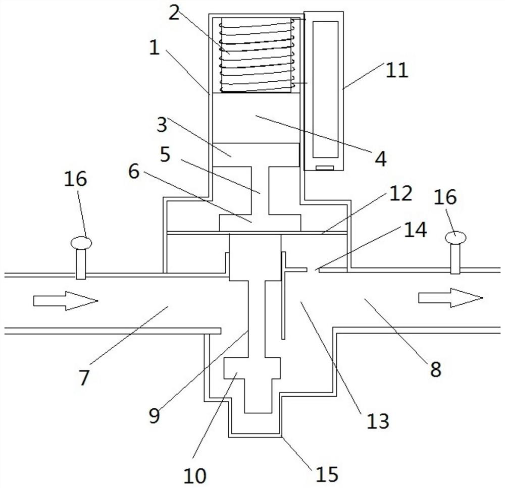
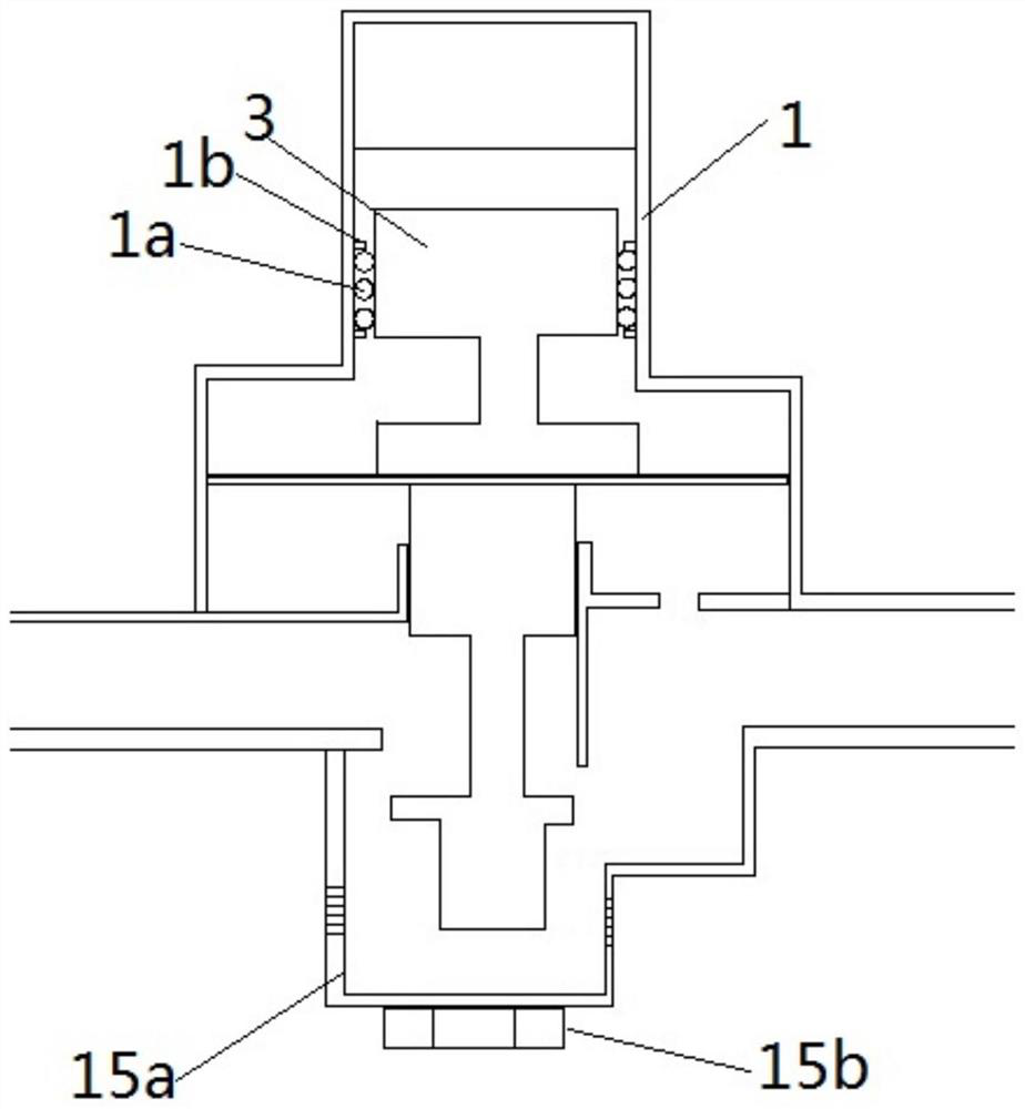
The invention discloses an efficient gas pressure reducing device. The lower end of a high-pressure pipeline is communicated with the lower end of a low-pressure pipeline through a second shell, a valve hole with the size adjusted through vertical movement of a valve head is formed in the second shell, a damping cavity is formed in the bottom of the first shell, and a pipe hole used for vertical movement of a piston at the top of an air valve rod to be through is formed in the middle of the damping cavity; the piston at the top of the air valve rod is connected with a diaphragm, the diaphragmisolates a first shell inner cavity space on the upper portion of the diaphragm from a first shell damping cavity on the lower portion of the diaphragm, the damping cavity is isolated from the high-pressure pipeline and communicated with the low-pressure pipeline through a damping hole, and a diaphragm rod fixing part is arranged in the first shell inner cavity space on the upper portion of the diaphragm and fixedly connected with the diaphragm; the diaphragm rod fixing part is further connected with a permanent magnet through a connecting rod, a first cavity is reserved in the first shell inner cavity in the upper portion of the permanent magnet, and an electromagnetic force assembly is arranged at the top of the first shell inner cavity; and the efficient gas pressure reducing device further comprises a circuit board, a circuit system used for controlling the electromagnetic force assembly is arranged in the circuit board, and the circuit system is electrically connected with the electromagnetic force assembly.

Description

technical field [0001] The invention relates to a gas decompression device, in particular to a high-efficiency gas decompression device. Background technique [0002] Conventional gas pressure reducing device technologies such as figure 1 The illustrated gas decompression device includes a high-pressure gas pipeline b7 and a low-pressure pipeline b8, and a decompression device is set between the high-pressure pipeline b7 and the low-pressure pipeline b8. The main principle is that when the gas pressure in the pipeline changes For example, the gas pressure in the high-pressure pipeline b7 suddenly increases, and the high pressure of the gas is transmitted to the damping hole b9 through the flow of the gas. The damping hole b9 is only set on the side of the low-pressure pipeline b8, and the increased high pressure directly leads to the upper side of the damping hole b9. The gas in the cavity squeezes the diaphragm b4, and after the diaphragm b4 is squeezed (the gas pressure i...

Claims


Application Information

Patent Timeline
Patent Type & Authority Applications(China)
IPC IPC(8): F16K31/08F16K31/06
CPCF16K31/082F16K31/0675Y02T10/30
Inventor 张济麟
Owner 泰安福星汽车配件有限公司
Learn More