Spinning window convenient to install and provided with dustproof structure

A technology of dust-proof structure and spinning window, applied in the field of spinning window, can solve the problems of inconvenient cleaning, inconvenient assembly and cleaning, inconvenient operation, etc.

Active Publication Date: 2020-12-22
FUJIAN JINJIANG TECH
View PDF10 Cites 1 Cited by
  • Summary
  • Abstract
  • Description
  • Claims
  • Application Information

AI Technical Summary

Problems solved by technology

[0002] Spinning is also called chemical fiber forming. The spinning window is a device on the spinning machine. The spinning machine is used for spinning polyester, nylon and polypropylene. The polymer melt is transported to the spinning machine by the booster pump through the pipeline. The filament box is metered by the melt metering pump and spun through the components. The tow encounters cold air in the spinning window to cool and solidify into fibers, and then it is wound and formed. Dust will be generated inside the spinning window after long-term work. Difficult to clean
[0003] The spinning window in the prior art is not easy to assemble and clean. The current spinning window is generally fixed on the wall with bolts and special glue, which is not convenient to operate, and it is not easy to install or disassemble. It will form dust accumulation inside. When cleaning, the whole spinning window needs to be disassembled and cleaned, which is inconvenient to clean. Moreover, the harmful gas in the nylon fabric is not completely eliminated in the existing spinning window while the internal tow is cooling, and a large amount of residue remains. Harmful gas inside, long-term work will cause harm to human health

Method used


Image

  • Spinning window convenient to install and provided with dustproof structure
  • Spinning window convenient to install and provided with dustproof structure
  • Spinning window convenient to install and provided with dustproof structure

Examples


Embodiment Construction

[0019] The present invention will be further described below in conjunction with the accompanying drawings.

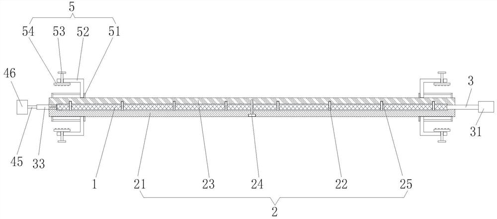
[0020] see Figure 1 to Figure 5 As shown, the present invention provides an embodiment: a spinning window that is easy to install and has a dust-proof structure, including a spinning window body 1, an assembly mechanism 2 is provided on the outside of the spinning window body 1, and the assembly mechanism 2 includes a first limit frame 21, a clamping rod 22, a second limit frame 23 and a bolt 24, the first limit frame 21 and the second limit frame 23 are respectively located on the front and rear sides of the spinning window body 1, The rear end surface of the first limiting frame 21 is fixed with the clamping rod 22, and the clamping rod 22 passes through the spinning window body 1 and is snap-connected to the front end surface of the second limiting frame 23. The outside of the assembly mechanism 2 is provided with an installation mechanism 5 for installing the spi...


PUM


Abstract

The invention provides a spinning window convenient to install and provided with a dustproof structure. The spinning window comprises a spinning window body; an assembling mechanism is arranged on theouter side of the spinning window body; the assembling mechanism comprises a first limiting frame, a clamping rod, a second limiting frame and bolts; the first limiting frame and the second limitingframe are located on the front side and the rear side of the spinning window body respectively; the clamping rod is fixed on the rear end face of the first limiting frame and penetrates through the spinning window body to be connected with the front end face of the second limiting frame in a clamped mode; an installation mechanism used for installing the spinning window in a wall is arranged on the outer side of the assembling mechanism; an air inlet pipe is installed above the right side of the exterior of the spinning window body, the air inlet pipe penetrates through the second limiting frame to be connected with the spinning window body, the air inlet pipe is fixedly connected with a draught fan, and meanwhile a spinneret plate is arranged at the top end of the interior of the spinningwindow body; the device is simple in structure, convenient to operate and install and capable of achieving the dustproof effect.

Description

technical field [0001] The invention relates to the technical field of spinning windows, in particular to a spinning window which is easy to install and has a dust-proof structure. Background technique [0002] Spinning is also called chemical fiber forming. The spinning window is a device on the spinning machine. The spinning machine is used for spinning polyester, nylon and polypropylene. The polymer melt is transported to the spinning machine by the booster pump through the pipeline. The filament box is metered by the melt metering pump and spun through the components. The tow encounters cold air in the spinning window to cool and solidify into fibers, and then it is wound and formed. Dust will be generated inside the spinning window after long-term work. Difficult to clean. [0003] The spinning window in the prior art is not easy to assemble and clean. The current spinning window is generally fixed on the wall with bolts and special glue, which is not convenient to ope...

Claims


Application Information

Patent Timeline
IPC IPC(8): D01D13/02
CPCD01D13/02
Inventor 陈信富郑祥盘张巧珍
Owner FUJIAN JINJIANG TECH
Why Eureka
Try Eureka