Electromagnetic switching-valve position detection system

An electromagnetic switching valve and detection system technology, which is applied in the direction of electric/magnetic position measurement, electromagnetic measuring device, electromagnetic circuit device, etc., can solve the problems of electromagnetic switching valves such as variable length and large size, and achieve improved responsiveness and S/N ratio, to achieve the effect of switching speed

Active Publication Date: 2020-12-18
YUKEN KOGYO
View PDF7 Cites 0 Cited by
  • Summary
  • Abstract
  • Description
  • Claims
  • Application Information

AI Technical Summary

Problems solved by technology

[0005] In order to improve the reliability of the switching movement of the solenoid-based spool, the above-mentioned detection mechanism and sensor are required, but since these devices are installed, the electromagnetic switching valve Overall lengthening and large-scale are unavoidable

Method used


Image

  • Electromagnetic switching-valve position detection system
  • Electromagnetic switching-valve position detection system
  • Electromagnetic switching-valve position detection system

Examples


Embodiment Construction

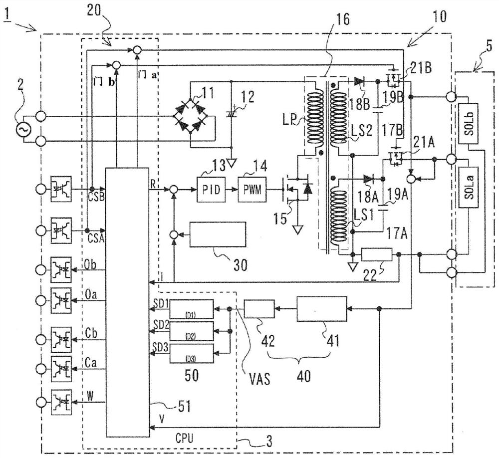
[0034]The electromagnetic switch valve position detection system of the present invention is used as a position detection system for an electromagnetic switch valve in which the flow path of the hydraulic circuit is switched by displacing the valve core by the movable iron core that is attracted and moved to the fixed iron core by energizing and exciting the solenoid. A system comprising: a current control circuit comprising a bridge diode, a primary-side smoothing capacitor, a switching transformer, a secondary-side diode, and a secondary-side smoothing capacitor, the bridge diode to which the current flows from a power supply is alternating current. Perform rectification, make it non-polarized in the case of direct current, the primary side smoothing capacitor smoothes the direct current from the bridge diode, and the switching transformer will pass to be based on the period of the pulse signal from the pulse signal generating device The ON / OFF switching of the switching elem...


PUM


Abstract

This electromagnetic switching-valve position detection system is provided with: a current control circuit that obtains a smoothed direct current by smoothing a current from a power source via a rectifier bridge diode and a primary-side smoothing capacitor, that transmits the direct current to the secondary side by a switching transformer as an alternating current of pulse waves from a switching element where switching is controlled in accordance with a pulse signal from a pulse signal generation device, and that outputs same as a direct current that has been smoothed via a secondary-side diode and a secondary-side capacitor; a carrier wave generation device for superimposing high-frequency carrier waves for position detection onto signal waves of a current command; and a detection unit for extracting a frequency component of the carrier waves from a voltage feedback signal of a solenoid, and detecting a voltage amplitude thereof to obtain an amplitude signal. A control unit further comprises: a position determination unit for determining a valve spool position on the basis of the amplitude signal and preset criterion reference values corresponding to respective valve spool positions, and outputting a determination signal; and a determination circuit for outputting a valve position signal on the basis of the determination signal.

Description

technical field [0001] The present invention relates to a system for detecting the position of an electromagnetic switching valve by detecting the position of a spool valve without using a position detection sensor. Background technique [0002] In the electromagnetic switching valve used in the hydraulic system, the coil of the solenoid is generally energized to make the movable iron core move toward the fixed iron core, so that the position of the valve core linked with the movable iron core is in the axial direction. The upward displacement and the port connection are switched, switching the flow path of the hydraulic circuit. [0003] Examples of such electromagnetic switching valves include a single solenoid type including one solenoid at one end of the valve element, and a double solenoid type including a pair of solenoids at both ends of the valve element. In the single solenoid type, in general, the so-called spring bias type in which the spool returns to a predeter...

Claims


Application Information

Patent Timeline
Patent Type & Authority Applications(China)
IPC IPC(8): F16K31/06F16K37/00H01F7/16H01F7/18
CPCH01F2007/185H01F2007/1855H01F2007/1888F16K37/0041F16K37/0083F16K31/0613H01F7/064G01B7/003
Inventor 永野卓
Owner YUKEN KOGYO
Why Eureka
Try Eureka