High-frequency NO-PLIF imaging measurement device and method

A NO-PLIF, imaging measurement technology, used in measurement devices, color/spectral property measurement, material analysis by optical means, etc. , poor light stability, etc., to achieve the effect of high spatial resolution and temporal resolution

Active Publication Date: 2020-12-18
SHANGHAI JIAO TONG UNIV
View PDF5 Cites 2 Cited by
  • Summary
  • Abstract
  • Description
  • Claims
  • Application Information

AI Technical Summary

Problems solved by technology

[0008] The existing NO planar laser-induced fluorescence (NO-PLIF) technology mostly uses low-frequency repetitive lasers. Compared with high-frequency NO-PLIF, it aims at the time resolution and spatial resolution of the combustion pollutant NO quantitative measurement of unstable combustion organization. The rate is not high
At the same time, the existing technology multi-purpose dye laser is loaded into C450 dye solution to generate fundamental frequency light with a wavelength of about 450nm, which is frequency-multiplied to 225nm by the frequency conversion unit for NO fluorescence induction, but the dye laser has low laser efficiency, poor photostability, and damage threshold. Low, not suitable for ultra-high repetition rate systems and other issues

Method used


Image

  • High-frequency NO-PLIF imaging measurement device and method
  • High-frequency NO-PLIF imaging measurement device and method
  • High-frequency NO-PLIF imaging measurement device and method

Examples


Embodiment Construction

[0055] Preferred embodiments of the present invention will be described in detail below in conjunction with the accompanying drawings, so as to better understand the purpose, features and advantages of the present invention. It should be understood that the embodiments shown in the drawings are not intended to limit the scope of the present invention, but only to illustrate the essence of the technical solutions of the present invention.

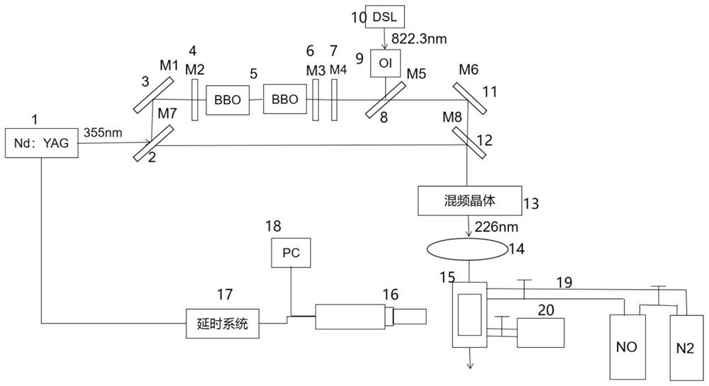
[0056] figure 1 A schematic diagram of the high-frequency NO-PLIF imaging measurement experimental device of the present invention is shown. Among them, the high-frequency NO-PLIF imaging measurement experiment equipment includes a high-frequency laser 1, a first mirror 2, a first mirror 3, a third mirror 4, a BBO crystal 5, a fourth mirror 6, a fifth mirror 7, a second Lens 8, optical isolator (OI, Optical isolator) 9, seed laser (DSL) 10, second mirror 11, third mirror 12, mixing crystal (mixing crystal) 13, convex lens 14, standard gas p...


PUM

PropertyMeasurementUnit
Wavelengthaaaaaaaaaa
Line widthaaaaaaaaaa

Abstract

;The invention relates to a high-frequency NO-PLIF imaging measurement device and method for a combustion field, and the device comprises a high-frequency laser which is used for generating 1064nm laser with the repetition frequency of 100kHz and outputting 355nm laser after triple frequency multiplication of the 1064nm laser, wherein the 355nm laser is divided into a first 355nm laser beam and asecond 355nm laser beam through a first lens a seed laser module which is used for generating 822.3 nm seed laser; an optical parametric oscillator which is used for converting the first beam of 355 nm laser input by the high-frequency laser and the 822.3 nm laser input by the seed laser module to generate 624.7 nm laser; an NO-PLIF module which is used for synthesizing 624.7 nm laser input by theoptical parametric oscillator and a second beam of 355 nm laser input by the high-frequency laser into 226 nm light, wherein the 226 nm light is gathered in a standard gas pool through a convex lensto react with NO to generate a PLIF optical signal; and an imaging measurement module which is used for imaging the PLIF optical signal and then processing the PLIF optical signal in the computer to obtain the flame temperature of the combustion field to be measured.

Description

technical field [0001] The invention belongs to the field of combustion diagnosis, and in particular relates to a high-frequency NO-PLIF imaging measurement device and method. Background technique [0002] Combustion is a rapid and violent process of luminescence and heat generated by the interaction of flow, heat transfer, mass transfer and chemical reaction. It is a complex physical and chemical phenomenon, usually accompanied by sudden changes in the properties of the system in space or time, especially are chemical composition and temperature. The combustion process is the main way of energy generation in the world. At present, more than 80% of the world's energy and power come from the combustion of fuels. It can be said that combustion is crucial to the operation of society. Although after several centuries of development, combustion has a fairly mature technology, but the emission of pollutants related to combustion has caused troubles to the wider use of combustion....

Claims


Application Information

Patent Timeline
IPC IPC(8): G01N21/39G01N21/01
CPCG01N21/39G01N21/01
Inventor 刘训臣张昊原曹健王震齐飞
Owner SHANGHAI JIAO TONG UNIV
Why Eureka
Try Eureka