
An anti-floating anchor pile connecting device

A technology of anti-floating anchor rods and pile barrels, which is applied in hoisting devices, protection devices, lifting equipment braking devices, etc., and can solve problems such as waste of resources and environmental pollution

Active Publication Date: 2021-09-14
北京中兵岩土工程有限公司
View PDF0 Cites 0 Cited by
  • Summary
  • Abstract
  • Description
  • Claims
  • Application Information

AI Technical Summary

Problems solved by technology

[0005] In order to improve the serious defects of environmental pollution and resource waste after pile connection, the application provides an anti-floating anchor pile connection device

Method used


Image

  • An anti-floating anchor pile connecting device
  • An anti-floating anchor pile connecting device
  • An anti-floating anchor pile connecting device

Examples


Embodiment 1

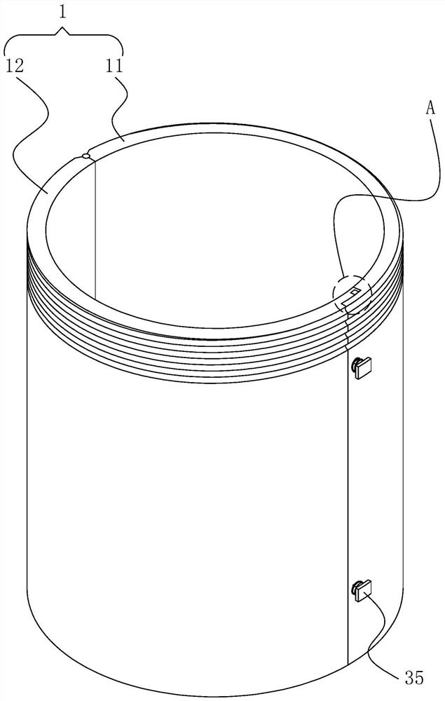
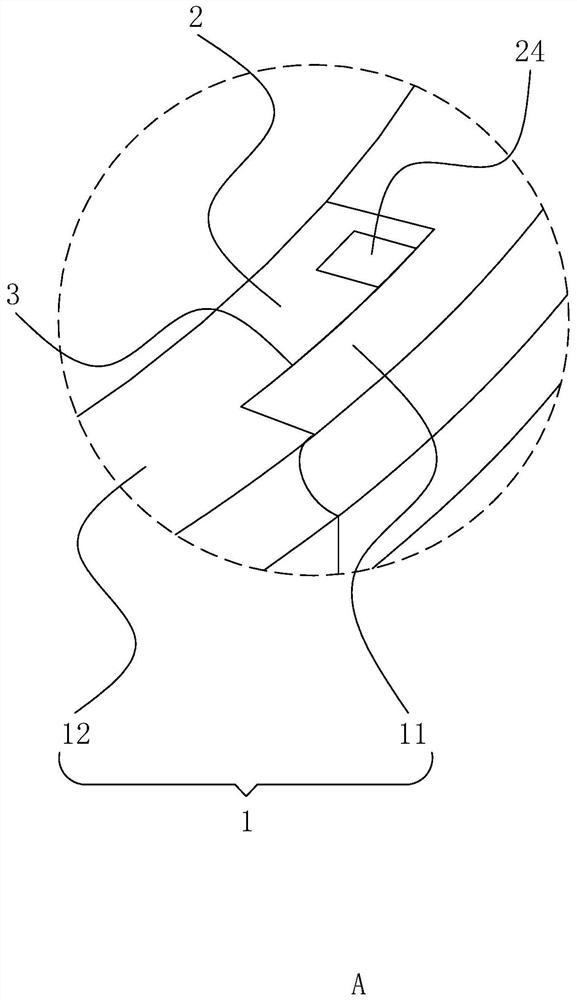
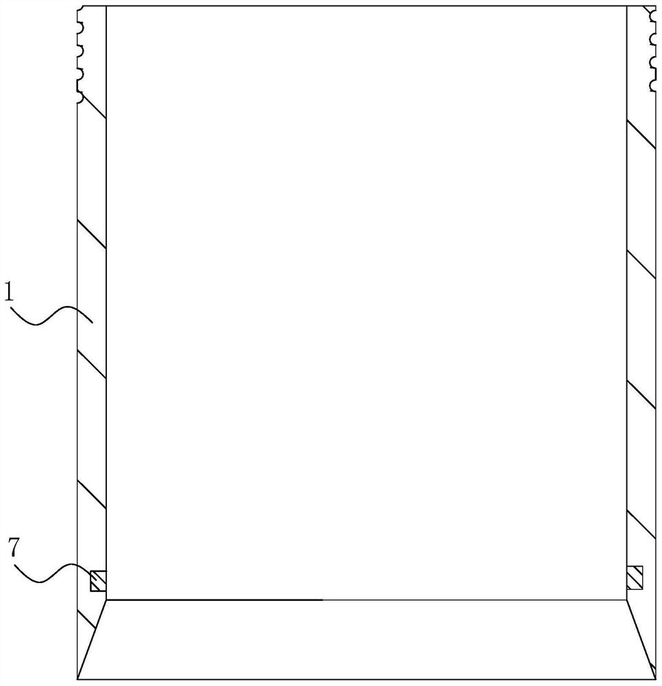
[0043] refer to figure 1 and figure 2 , a borehole is vertically opened on the ground, and the original pile head is fixed in the borehole, and a number of anti-floating anchor rods are fixedly inserted in the original pile head, and the top of the anti-float anchor rod extends 4 holes and bends outwards. The anti-floating anchor pile receiving device includes a pile connecting tube 1 that is vertically arranged and opened up and down. The pile connecting tube 1 is divided into a first arc plate 11 and a second arc plate 12 along the vertical direction, and the first arc plate 11 and the second arc plate 12 One side of the second arc plate 12 is hinged, and the hinge axis is vertically arranged. The end of the first arc plate 11 away from its hinge is provided with an arc-shaped dismounting groove 3, and the end of the second arc plate 12 away from its hinge is fixedly connected. There is an arc-shaped dismounting plate 2, a dismounting groove 3 for the dismounting plate 2 t...

Embodiment 2

[0050] refer to Figure 7 The difference between this embodiment and Embodiment 1 is that a connecting assembly is provided between the connecting cylinder 45 and the pile receiving cylinder 1, and the connecting assembly includes a flashing plate 5, a locking bar 53, a fixing spring 54 and a fixing plate 55, and the flashing plate 5 Slidingly connected to the lower end surface of the connecting cylinder 45, the top of the peripheral outer wall of the pile connecting cylinder 1 is provided with a slot 51 for inserting one end of the inserting plate 5, and the bottom end of the peripheral outer wall of the connecting cylinder 45 is provided with a fixing groove 6 The lower surface of the flashboard 5 is vertically provided with a fixing hole 52 connected to the fixing groove 6, the top of the outer wall of the locking bar 53 is hinged to one end of the fixing plate 55, and the angle between the fixing plate 55 and the locking bar 53 is an acute angle. The fixed spring 54 is fix...


PUM


Abstract

The application relates to an anti-floating anchor pile connecting device, which includes a pile connecting barrel, which is set with upper and lower openings, and the pile connecting barrel includes a first arc plate and a second arc plate, and the first arc plate and the second arc plate One side of the length direction is hinged to each other, the hinge axis is consistent with the length direction of the pile barrel, the end of the first arc plate away from the hinge is provided with a disassembly slot, and the end of the second arc plate away from the hinge is fixedly connected with a disassembly slot Plate, dismounting slot for the dismounting plate to insert, between the dismounting plate and the dismounting slot there is a dismounting assembly for disassembling the first arc plate and the second arc plate, the pile connecting tube is located in the borehole, and the pile connecting tube The bottom end of the original pile head is wrapped and attached to it, the top of the pile barrel extends out of the ground, and a lifting device for lifting the pile barrel out of the borehole is provided above the pile barrel. This application has the advantages of reducing environmental pollution and resources wasteful effect.

Description

technical field [0001] The present application relates to the technical field of anti-floating anchors, in particular to an anti-floating anchor pile connection device. Background technique [0002] With the three-dimensional and in-depth development of construction projects, more and more anti-floating anchor designs are used in anti-floating projects; the success or failure of the anti-floating anchor construction quality is related to the safety and reliability of the entire main structure; and the anti-floating anchor construction During the process, it is easy for the cement pouring to fail to reach the design elevation or the pile head is damaged when the soil between the piles is cleaned, which will affect the quality of the anti-floating anchor rod, and then affect the safety and reliability of the entire main structure, so pile connection must be carried out. [0003] Existing anti-floating anchor piles are cut with PVC pipes according to the actual size, and then t...

Claims


Application Information

Patent Timeline
Patent Type & Authority Patents(China)
IPC IPC(8): E02D5/52E02D5/54E02D31/12B66C5/02B66C1/62
CPCB66C1/62B66C5/02E02D5/526E02D5/54E02D31/12E02D2200/146E02D2600/20
Inventor 朱海涛白忠杰赵杰伟刘长松周宸张丹许超
Owner 北京中兵岩土工程有限公司
Learn More