Jig for machining blade crown of engine blade and machining method of engine blade

A technology of engine blades and processing methods, which is applied to metal processing machinery parts, manufacturing tools, metal processing equipment, etc., can solve the problems such as the quality of blade crowns cannot be guaranteed, and achieve shortened processing procedures, not easy to twist or vibrate, milling good rigidity

Active Publication Date: 2021-12-10
AECC AERO SCI & TECH CO LTD
View PDF10 Cites 0 Cited by
  • Summary
  • Abstract
  • Description
  • Claims
  • Application Information

AI Technical Summary

Problems solved by technology

[0007] The object of the present invention is to provide a jig for machining the blade crown of the engine blade and a processing method for the engine blade, so as to solve the problem that the quality of the existing blade crown cannot be guaranteed after processing

Method used


Image

  • Jig for machining blade crown of engine blade and machining method of engine blade
  • Jig for machining blade crown of engine blade and machining method of engine blade
  • Jig for machining blade crown of engine blade and machining method of engine blade

Examples


Embodiment

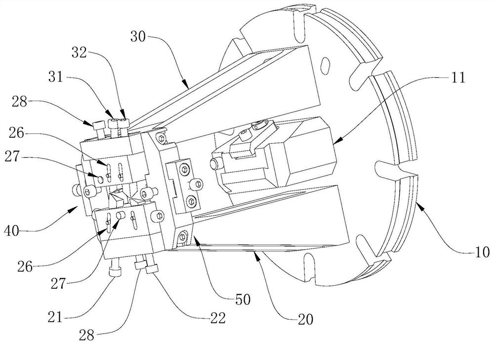
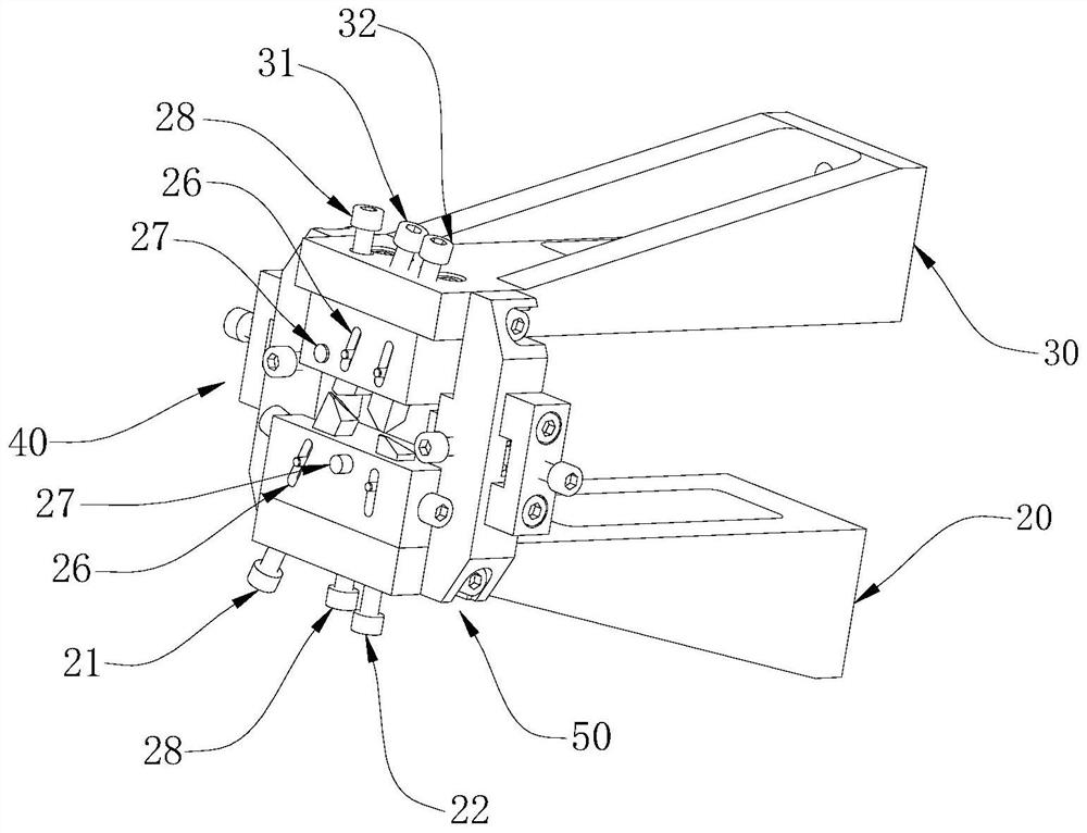
[0052] The jig for machining the crown of the engine blade includes: a first support block 20 and a second support block 30 , the first support block 20 and the second support block 30 are perpendicular to the machine tool positioning plate 10 and installed on the machine tool positioning plate 10 . The structure of the first support block 20 and the second support block 30 is consistent, and the first support block 20 and the second support block 30 are oppositely arranged on both sides of the jaw 11 on the machine positioning plate 10, the first support block 20 and the second support block Each block 30 includes a connecting end connected to the machine tool positioning plate 10 through bolts and a positioning end away from the machine tool positioning plate 10 . The positioning end of the first support block 20 is used to cooperate with the convex surface of the blade airfoil, and the convex surface of the blade airfoil is limited, and the positioning end of the second supp...


PUM


Abstract

The invention discloses a jig for processing a crown of an engine blade and a processing method for the engine blade, belonging to the technical field of aeroengines. A jig for machining a blade crown of an engine blade, comprising a first support block and a second support block oppositely arranged, and the first support block and the second support block jointly limit the position of the blade body close to the blade crown, by The "false tip" replaces the original tip to clamp and fix the blade. The distance between the blade crown and the "pseudo tip" is small, and the milling rigidity of the blade crown is good, which reduces the impact caused by the blade and vibration, and avoids It solves the problem that the vane shroud is squeezed through the axial positioning of the tip, resulting in part deformation and offset positioning surface. The technical goals of the blade shroud in processing and measurement are consistent, which improves the detection accuracy and reversely guarantees the accuracy of the blade. Processing quality of leaf crown.

Description

technical field [0001] The invention relates to the technical field of aero-engines, in particular to a jig for machining a crown of an engine blade and a machining method for the engine blade. Background technique [0002] In order to meet the high-power and high-efficiency requirements of the new generation of aero-engines, blades are the core components. The structure of aero-engines has a breakthrough innovation compared with the old models. Compared with the previous blades, its structure is relatively complex and technical requirements relatively higher. [0003] When processing the blade crown, it has the characteristics of complex structure, poor blade rigidity, large cold deformation, many related dimensions and high technical requirements. The main positioning datum is to withstand the crown of the blade through the tip, and fix it by clamping at both ends, so that the crown of the blade has the following technical defects in the process of processing: [0004] 1...

Claims


Application Information

Patent Timeline
Patent Type & Authority Patents(China)
IPC IPC(8): B23Q3/00B23C3/18
CPCB23Q3/00B23C3/18B23Q2703/10
Inventor 邓明忠唐波张涛孟军
Owner AECC AERO SCI & TECH CO LTD
Why Eureka
Try Eureka