Annular groove riveting machine

A technology of ring groove rivets and riveting machines, applied in the field of ring groove rivet machines, can solve the problems such as affecting the safety of ring groove rivet installation, inability to adjust the joints of ring groove rivet machines, and reducing the efficiency of ring groove rivet installation.

Inactive Publication Date: 2020-12-18
杨清云
View PDF0 Cites 0 Cited by
  • Summary
  • Abstract
  • Description
  • Claims
  • Application Information

AI Technical Summary

Problems solved by technology

[0004] Aiming at the deficiencies in the prior art, the purpose of the present invention is to provide a ring groove rivet machine to solve the problem that when the ring groove rivets are nailed, the ring groove rivets are made of high-quality carbon steel, and the riveting strength is high and firm. Reliable, when processing, because the joint of the ring groove rivet machine cannot be adjusted, when the joint of the ring groove rivet machine is connected with the ring groove rivet, the joint of the groove rivet machine is smaller than the ring groove rivet, resulting in joints Compared with the ring groove rivet, the contact area of ​​the nailing surface is smaller. During the nailing process, the spout will be tilted due to the contact of the nailing surface, and the rivet will be sprayed crookedly, which will cause the nail sleeve to be squeezed and deformed during riveting. Rivets are prone to breakage, which affects the safety of ring groove rivets and reduces the efficiency of ring groove rivets.

Method used


Image

  • Annular groove riveting machine
  • Annular groove riveting machine
  • Annular groove riveting machine

Examples


Embodiment 1

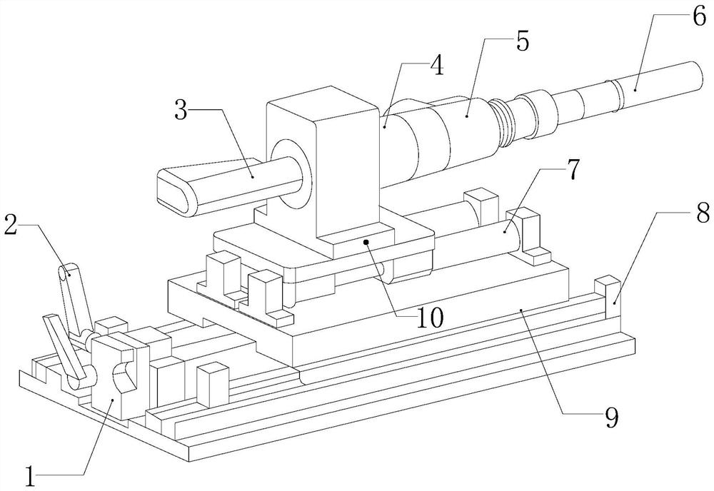
[0032] see figure 1, the present invention provides a technical solution: a ring groove rivet machine, its structure includes a guide rail 1, a lock 2, a pressure pipe 3, a nozzle 4, an adjustment device 5, a ring groove rivet 6, a slide rail 7, and a body 8 , workbench 9, moving seat 10, the guide rail 1 is installed on the body 8, the guide rail 1 is embedded and fixed on the body 8 in parallel, a lock 2 is provided on one side of the guide rail 1, and the lock 2 fits On one side of the guide rail 1, a workbench 9 is provided on the guide rail 1, and the workbench 9 is engaged with the guide rail 1, and a slide rail 7 is arranged on the top of the workbench 9, and the slide rail 7 is installed by a fixing member On the worktable 9, the slide rail 7 is buckled on the workbench 9 in parallel, and the slide rail 7 is provided with a moving seat 10, and the moving seat 10 and the slide rail 7 are engaged in a movable engagement manner, and the The moving base 10 is provided wi...

Embodiment 2

[0042] see figure 1 , the present invention provides a technical solution: a ring groove rivet machine, its structure includes a guide rail 1, a lock 2, a pressure pipe 3, a nozzle 4, an adjustment device 5, a ring groove rivet 6, a slide rail 7, and a body 8 , workbench 9, moving seat 10, the guide rail 1 is installed on the body 8, the guide rail 1 is embedded and fixed on the body 8 in parallel, a lock 2 is provided on one side of the guide rail 1, and the lock 2 fits On one side of the guide rail 1, a workbench 9 is provided on the guide rail 1, and the workbench 9 is engaged with the guide rail 1, and a slide rail 7 is arranged on the top of the workbench 9, and the slide rail 7 is installed by a fixing member On the worktable 9, the slide rail 7 is buckled on the workbench 9 in parallel, and the slide rail 7 is provided with a moving seat 10, and the moving seat 10 and the slide rail 7 are engaged in a movable engagement manner, and the The moving base 10 is provided w...


PUM


Abstract

The invention discloses an annular groove riveting machine which structurally comprises a guide rail, a locking piece, a pressure applying pipe, a spraying pipe, an adjusting device, annular groove rivets, a sliding rail, a machine body, a workbench and a movable base. When the annular groove riveting machine is used after improvement, the annular groove rivets are inserted into clamping and fixing cavities in a penetrating mode, and clamping blocks can drive movable rods to be unscrewed outwards under the thrust of the clamping and fixing cavities, and accordingly, the annular groove rivets can be stably inserted and embedded in the clamping and fixing cavities. Anti-skid plates can increase the resistance between buckling blocks and the clamping and fixing cavities, it is guaranteed thatthe annular groove rivets cannot slide when clamped, pressing rods bear the external thrust of opening and closing clamping pieces, the force is guided to extrusion blocks, so that suction blocks areconnected to a movable disc, and the opening and closing clamping pieces can clamp and fix the annular groove rivets easily. When the opening and closing clamping pieces extrude the pressing rods, certain mutual exclusion force can be generated, pushing and pressing force is generated between the opening and closing clamping pieces and the pressing rods, the annular groove rivets can be stably clamped and connected to the spraying pipe for nailing, the annular groove rivets are stably nailed at the operation position, and the nailing effect of the annular groove rivets is improved.

Description

technical field [0001] The invention relates to the field of automatic special machines, in particular to a ring groove riveting machine. Background technique [0002] The ring groove rivet machine is an automatic rivet injection equipment, which can spray the rivets on the fixed point by means of air pressure to fix them. The ring groove rivet is composed of a nail rod and a nail sleeve. The material of the nail rod is titanium alloy. When installing ring groove rivets, adjust the size of the joint through the adjusting element, so that the contact area of ​​the nailing surface becomes larger, and the rivets can be stably loaded. When nailing ring groove rivets, what needs to be improved : [0003] When fixing the ring groove rivets, the ring groove rivets are made of high-quality carbon steel. The riveting strength is high, firm and reliable. When the joint of the rivet machine is connected with the ring groove rivet, the joint of the groove rivet machine is smaller than...

Claims


Application Information

Patent Timeline
Patent Type & Authority Applications(China)
IPC IPC(8): B21J15/10B21J15/18B21J15/32
CPCB21J15/10B21J15/18B21J15/32
Inventor 杨清云
Owner 杨清云
Why Eureka
Try Eureka