MEMS microphone and manufacturing method thereof

A manufacturing method and microphone technology, applied in the directions of loudspeakers, electrostatic transducer microphones, sensors, etc., can solve the problems of poor acoustic performance and low signal-to-noise ratio of MEMS microphones, so as to improve product performance, shorten lamination time, The effect of reducing production costs

Pending Publication Date: 2020-12-15
华天慧创科技(西安)有限公司
View PDF0 Cites 0 Cited by
  • Summary
  • Abstract
  • Description
  • Claims
  • Application Information

AI Technical Summary

Problems solved by technology

[0005] In order to solve the problems existing in the prior art, the present invention provides a MEMS microphone and its manufacturing method to solve the problems of low signal-to-noise ratio and poor acoustic performance of the existing MEMS microphones

Method used


Image

  • MEMS microphone and manufacturing method thereof
  • MEMS microphone and manufacturing method thereof
  • MEMS microphone and manufacturing method thereof

Examples


Embodiment

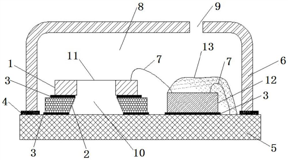
[0048] A method of manufacturing a MEMS microphone, comprising the following steps,

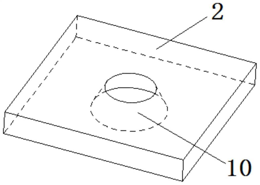
[0049] Step 1, bonding the MEMS chip 11 and the base 2 together to form a combined chip with a rear cavity 10;

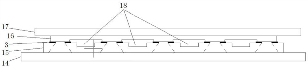
[0050] In step 1, two process types of wafer to wafer and chip to wafer are used for bonding the MEMS chip 11 and the base 2;

[0051] Such as image 3 and Figure 4 As shown, it is a wafer to wafer process type, and the MEMS chip 12 and the base 2 are all wafers, such as image 3 As shown, it may be first to place the small hole end of the base wafer 15 upward on the carrier 14, then suck the MEMS chip wafer 16 through the suction nozzle 17, and place the MEMS chip wafer 16 on the base wafer 15 in an aligned position. The above is pressed and fixed by the fixing glue 3. After the pressing is completed, the wafer cutting machine is used to cut at the position of the dicing line 18 to form a single combined chip, such as Figure 7 shown.

[0052] Such as Figure 4 As shown, th...


PUM


Abstract

The invention provides an MEMS microphone. The MEMS microphone comprises a circuit board, an MEMS chip, an ASIC chip, a base and a packaging cover, the base is provided with a through hole, the through hole is divided into a large hole end and a small hole end, and the opening area of the large hole end is larger than that of the small hole end; and the bottom silicon substrate of the MEMS chip isof a cavity structure; the silicon substrate is fixedly arranged on one side of the small hole end on the base, and the cavity corresponds to the small hole end on the base to form a rear cavity; thebase is fixedly arranged on the circuit board; the ASIC chip is fixedly arranged on the circuit board, the MEMS chip is electrically connected with the ASIC chip, the ASIC chip is electrically connected with the circuit board, the packaging cover is fixedly arranged on the circuit board and wraps the MEMS chip and the ASIC chip to form a front cavity, and a sound hole is formed in the packaging cover. The cavity on the silicon substrate is communicated with the through hole, so the volume of the rear cavity is increased, the volume difference between the front cavity and the rear cavity is reduced, the signal-to-noise ratio of the microphone is improved, and the acoustic performance is greatly improved.

Description

technical field [0001] The invention belongs to the field of micro-microphones, in particular to a MEMS microphone. Background technique [0002] MEMS (Micro Electro Mechanical System, Micro Electro Mechanical System) microphone is a microphone manufactured based on MEMS technology. Due to the advantages of small size, high sensitivity, and good compatibility with existing semiconductor technologies, MEMS microphones are more and more widely used in mobile terminals such as mobile phones. [0003] The structure of the MEMS microphone includes a diaphragm and a back plate electrode facing each other, which are respectively connected to corresponding electrodes via lead wires. A cavity is formed between the diaphragm and the back plate electrode to provide the required vibration space for the diaphragm. There are two cavities in the existing MEMS packaging structure, wherein a cavity formed between the circuit board and the package cover is the front cavity, and a cavity for...

Claims


Application Information

Patent Timeline
Patent Type & Authority Applications(China)
IPC IPC(8): H04R19/04H04R31/00
CPCH04R19/04H04R31/00H04R2201/003
Inventor 周浩邱山峰陈侠然邵雷王晓锋孔志浩
Owner 华天慧创科技(西安)有限公司
Why Eureka
Try Eureka