Method for Amplitude/Phase Correlation Joint Detection of Response Signal

A phase correlation and response signal technology, applied in the direction of measuring devices, radio wave measurement systems, radio wave reflection/reradiation, etc., can solve amplitude fading, amplitude and phase distortion, affect single pulse processing and receive sidelobe suppression processing Accuracy and other issues to achieve the effect of avoiding false alarms or missed alarms

Active Publication Date: 2022-07-29
10TH RES INST OF CETC
View PDF0 Cites 0 Cited by
  • Summary
  • Abstract
  • Description
  • Claims
  • Application Information

AI Technical Summary

Problems solved by technology

When the system has different gain amplitudes for different frequency components of the input signal, and the relative phase shift also changes at the same time, the output waveform is distorted, and the amplitude and phase of the output response are distorted
There are two disadvantages of this method. One is that under the condition of low signal-to-noise such as sensitivity, false alarms or missing alarms may occur when only the phase method is used to detect or the amplitude is used alone to detect the correlation peak of the target response signal; the other is that when the signal modulation When the mode is non-constant-envelope modulation, the pulse amplitude of the baseband signal directly obtained is not constant, and the amplitude will decline greatly at the moment of symbol conversion, which will affect the accuracy of single-pulse processing and receiving sidelobe suppression processing. Spend
At present, there are no domestic reports and materials on the application of the method of amplitude and phase correlation joint processing for target detection in the secondary radar system interrogator

Method used


Image

  • Method for Amplitude/Phase Correlation Joint Detection of Response Signal
  • Method for Amplitude/Phase Correlation Joint Detection of Response Signal
  • Method for Amplitude/Phase Correlation Joint Detection of Response Signal

Examples


Embodiment Construction

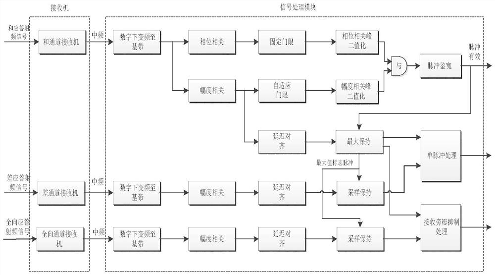
[0015] see figure 1 . According to the present invention, the interrogator in the secondary radar system transfers to the receiving state after transmitting the interrogation modulation signal, and the receivers on the sum channel, the difference channel and the omnidirectional channel receive the sum, difference and omnidirectional signals transmitted by the transponder. , down-converted to IF and then sent to the signal processing module. In the signal processing module, the 3-channel IF signals received by the sum channel, the difference channel and the omnidirectional channel are digitally down-converted to the baseband. In the large-scale programmable logic device FPGA The quadrature sine and cosine signals generated by the signal processing module DDS are multiplied by the intermediate frequency signal respectively, and the quadrature baseband signals I and Q are obtained through low-pass filtering, and the baseband signals of the three channels are phase correlated and ...


PUM


Abstract

The present invention proposes a method for jointly detecting a response signal with amplitude / phase correlation, and aims to provide a method capable of effectively detecting a coded modulated pulse signal. The present invention can be realized by the following scheme: in the signal processing module, digital down-converts the 3-way intermediate frequency signals received by the sum, difference and omnidirectional channels to the baseband, and uses DDS in the FPGA to generate quadrature sine and cosine signals, respectively. Multiply with the intermediate frequency signal, and then perform low-pass filtering to obtain the quadrature I-channel baseband signal and Q-channel baseband signal. According to the information coding codeword, the phase and amplitude correlation accumulation of the baseband signal is performed to form an aligned sum-channel phase correlation peak and amplitude. Correlation peak, the phase correlation peak and channel phase correlation peak are respectively subjected to fixed threshold judgment and amplitude correlation peak to adaptive threshold judgment processing to form a pulse binarized signal and a pulse effective signal, and then single pulse processing and receiving discrimination and suppression processing are performed to complete a single pulse. Detection of target response pulse signal.

Description

technical field [0001] The invention adopts the target detection method of amplitude and phase correlation joint processing in the secondary radar system interrogator to realize the detection of the secondary radar response pulse signal. More specifically, it is a target detection method that uses the amplitude correlation method and the phase correlation method to jointly detect the pulse correlation peak of the response signal, and uses the correlation peak amplitude to perform single pulse processing and receive sidelobe suppression in the interrogator signal processing process. Background technique [0002] In radar target detection, the problem of large targets obscuring small targets is often encountered. Generally, the RCS of a large civil airliner is more than one or two hundred square meters, and the RCS (Radar-CrossSection) of a small aircraft is between 1 and 2m. 2 between. If the distance between the two is very close, the intensity ratio of the echo is above 2...

Claims


Application Information

Patent Timeline
Patent Type & Authority Patents(China)
IPC IPC(8): G01S7/288G01S7/36G01S7/40G01S13/74
CPCG01S7/288G01S7/36G01S7/4021G01S13/74
Inventor 柳兵乔红
Owner 10TH RES INST OF CETC
Why Eureka
Try Eureka