A fault detection method, device and electrical equipment
A technology for fault detection and electrical equipment, applied in the direction of measuring devices, measuring electricity, measuring electrical variables, etc., can solve the problems of insufficient output voltage value of the drive circuit, drive faults, etc., to avoid insufficient output voltage value, improve stability and safety. sexual effect
- Summary
- Abstract
- Description
- Claims
- Application Information
AI Technical Summary
Problems solved by technology
Method used
Image
Examples
Embodiment 1
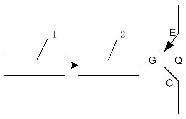
[0049] This embodiment provides a fault detection method, which is applied to a switch drive system, figure 1 It is a structural diagram of a switch driving system according to an embodiment of the present invention, such as figure 1 As shown, the switch drive system includes a drive circuit 1, a photocoupler 2, and a power switch tube Q connected in sequence. The power switch tube Q includes a gate G, an emitter E, and a collector C. The emitter E and the collector C are used for for access to the load circuit.
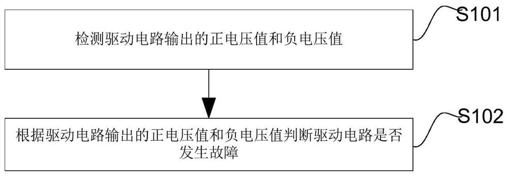
[0050] figure 2 It is a flowchart of a fault detection method according to an embodiment of the present invention, such as figure 2 As shown, the fault detection method includes:
[0051] S101. Detect the positive voltage value and the negative voltage value output by the drive circuit.
[0052] Since the drive circuit outputs two voltage values, positive voltage and negative voltage, to the optocoupler, if one of the voltage values is abnormal, the voltage o...
Embodiment 2
[0057] This embodiment provides another fault detection method. In order to ensure the accuracy of fault judgment, step S102 in the above embodiment specifically includes: if the positive voltage value satisfies the first preset condition, and the negative voltage value satisfies the second preset condition , it means that the voltage value output by the drive circuit is sufficient to drive the switch tube to act, and it is determined that the drive circuit has not failed; otherwise, it indicates that the output voltage value of the drive circuit is not enough to drive the switch tube to operate, and it is determined that the drive circuit has failed; wherein, the first preset The condition is: the positive voltage value is greater than or equal to the first threshold; the second preset condition is: the negative voltage value is less than or equal to the second threshold; the first threshold is positive, and the second threshold is negative, for example, the first threshold is ...
Embodiment 3
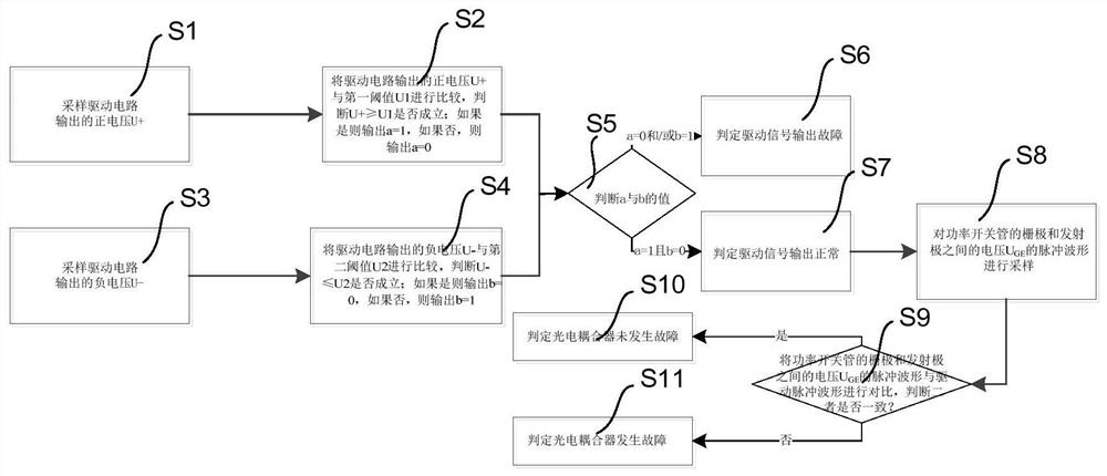
[0064] This embodiment provides another fault detection method, image 3 It is a flowchart of a fault detection method according to another embodiment of the present invention, such as image 3 As shown, the fault detection method includes:
[0065] S1, sampling the positive voltage U+ output by the driving circuit.
[0066] S2, comparing the positive voltage U+ output by the drive circuit with the first threshold U1, and judging whether U+≥U1 holds true; if yes, output a=1, and if not, output a=0.
[0067] S3, sampling the negative voltage U- output by the driving circuit.
[0068] S4, comparing the negative voltage U- output by the drive circuit with the second threshold U2, and judging whether U-≤U2 holds true; if yes, output b=0, and if not, output b=1.
[0069] S5, judge the values of a and b, if a=0 and / or b=1, execute step S6; if a=1 and b=0, execute step S7.
[0070] S6, determining that the drive signal output is faulty.
[0071] S7, determining that the drive ...
PUM
 Abstract
Description
Claims
Application Information
 - R&D
- Intellectual Property
- Life Sciences
- Materials
- Tech Scout
- Unparalleled Data Quality
- Higher Quality Content
- 60% Fewer Hallucinations
Browse by: Latest US Patents, China's latest patents, Technical Efficacy Thesaurus, Application Domain, Technology Topic, Popular Technical Reports.
© 2025 PatSnap. All rights reserved.Legal|Privacy policy|Modern Slavery Act Transparency Statement|Sitemap|About US| Contact US: help@patsnap.com


