Air duct air outlet structure and clothes nursing machine

An air duct and air duct technology, applied in the field of air duct outlet structure and clothing care machine, can solve the problems of prolonging nursing time, increasing humidification, accelerating product aging, etc., to improve airflow utilization efficiency, enhance speed and strength , the effect of increasing the wind speed

Pending Publication Date: 2020-12-15
GUANGZHOU SHIYUAN ELECTRONICS CO LTD +1
View PDF0 Cites 2 Cited by
  • Summary
  • Abstract
  • Description
  • Claims
  • Application Information

AI Technical Summary

Problems solved by technology

In this setting, since there is no special setting in the existing air outlet structure of the air duct, the distance between the air outlet and the clothes is relatively long, and the air outlet speed of the air outlet is low, resulting in low air velocity on the surface of the clothes and poor air utilization. Low, resulting in low efficiency of clothing care, deodorization and sterilization, so the effect must be achieved by prolonging the care time, increasing the amount of humidification, drying time, etc., which will not only consume more energy, but also bring inconvenience to consumers. Good experience accelerates product aging

Method used


Image

  • Air duct air outlet structure and clothes nursing machine
  • Air duct air outlet structure and clothes nursing machine
  • Air duct air outlet structure and clothes nursing machine

Examples


Embodiment 1

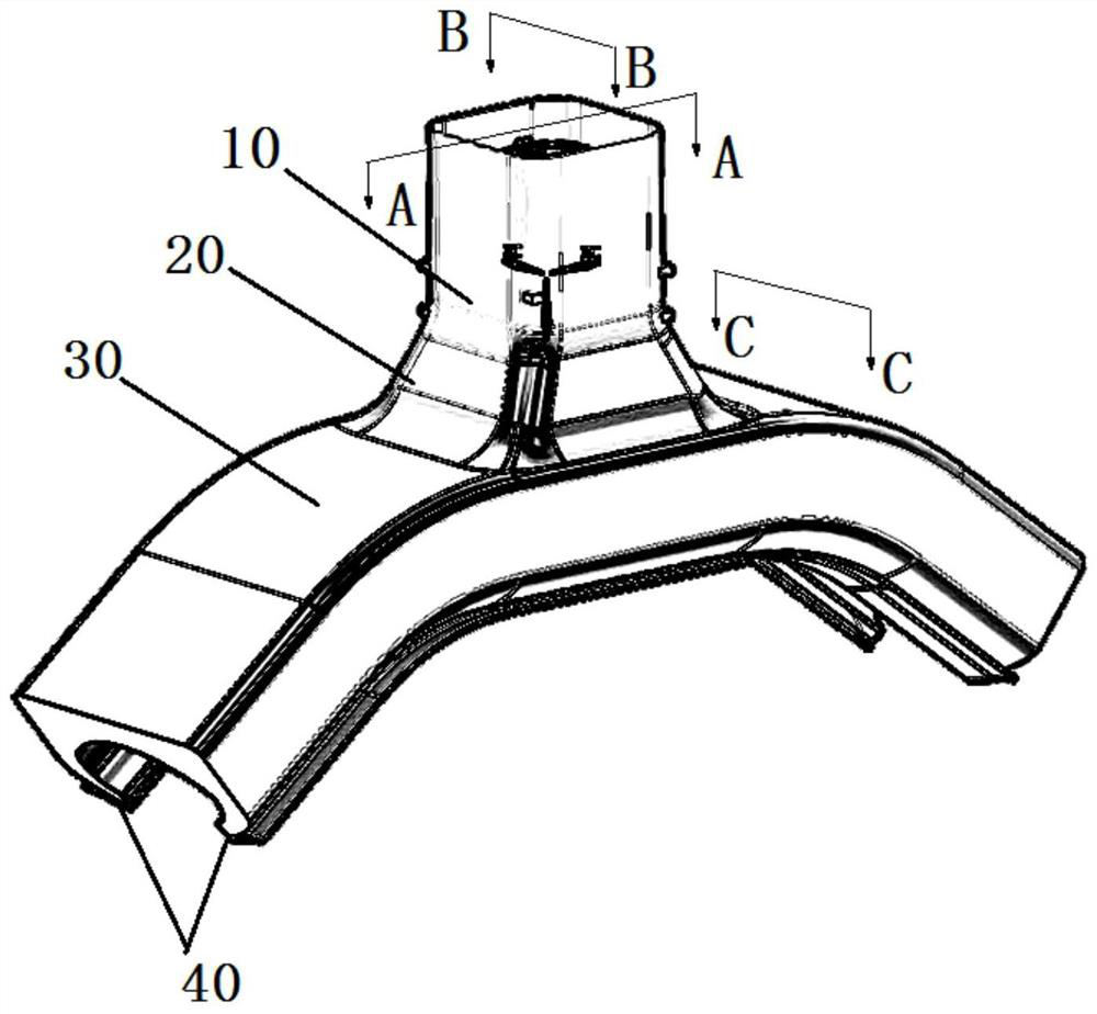
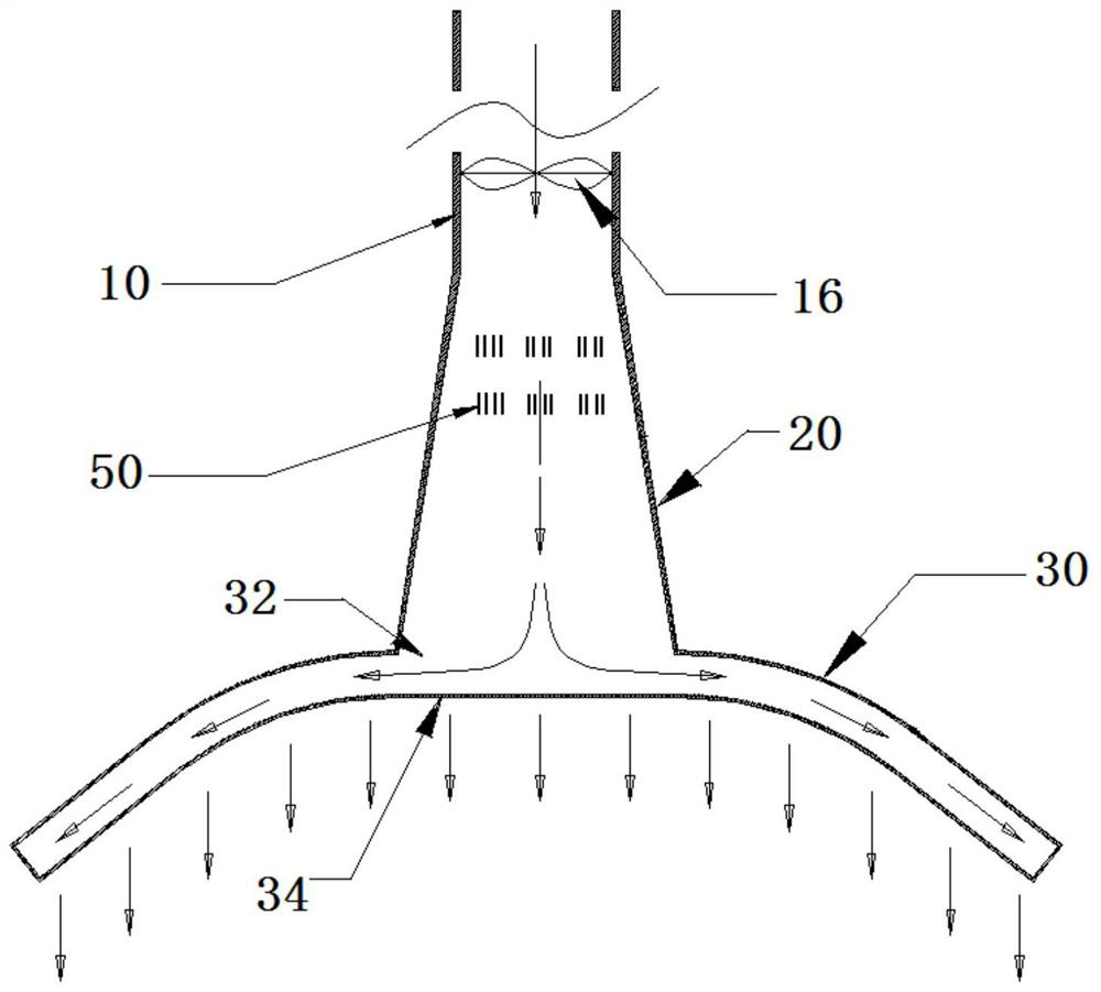
[0035] Please refer to Figure 1-4 , figure 1 It is a schematic diagram of the air outlet structure of the air duct according to Embodiment 1 of the present invention, figure 2 for figure 1 A schematic cross-sectional view of A-A is shown, image 3 for figure 1 The B-B cross-sectional schematic diagram shown, Figure 4 for figure 1 Schematic diagram of the C-C section shown. As shown in the figure, in view of the deficiencies in the prior art, Embodiment 1 of the present invention provides an air duct outlet structure, which includes an air inlet duct 10, a pressurized air duct 20, an induced air duct 30 and Jet duct 40.

[0036] A blower fan 16 is arranged in the air inlet duct 10, and the flow cross-sectional area of ​​the pressurized air duct 20 gradually increases along the air flow direction.

[0037] The air induction duct 30 includes an air inlet 32 ​​and an air outlet 34, and the air inlet 32 ​​communicates with the pressurized air duct 20; the number of the a...

Embodiment 2

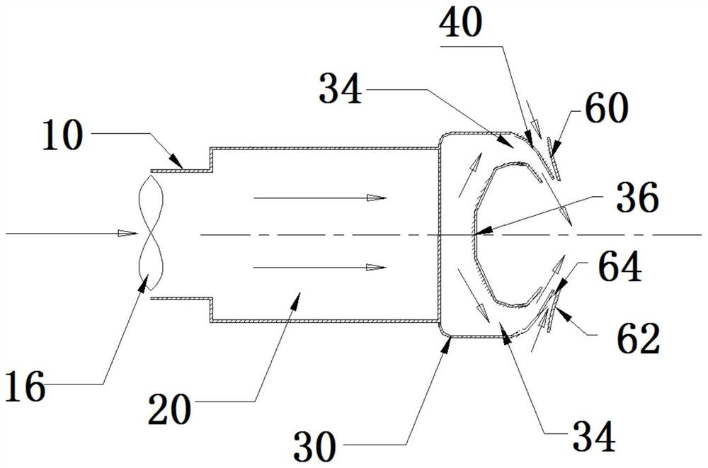
[0049] Please refer to Figure 8 , Figure 8 It is a partial cross-sectional view of the air duct outlet structure described in Embodiment 2 of the present invention. As shown in the figure, Embodiment 2 of the present invention provides an air duct outlet structure, which differs from Embodiment 1 in that: the injection air duct 40 includes The first air injection channel 401 , the throat 402 and the second air injection channel 403 are connected in sequence, and the first air injection channel 401 is in communication with the induced air channel 30 . The flow cross-sectional area of ​​the first air injection channel 401 gradually decreases along the air flow direction, the flow cross-sectional area of ​​the second air injection channel 403 gradually increases along the air flow direction, and the throat 402 is the cross-sectional area of ​​the flow in the air injection channel 40. Where the area is the smallest, its cross-sectional width is not less than 1 / 6 of the exit cro...

Embodiment 3

[0051] Please refer to Figure 9 , Figure 9 It is a partial cross-sectional schematic diagram of the air outlet structure of the air duct according to Embodiment 3 of the present invention. As shown in the figure, Embodiment 3 of the present invention provides an air outlet structure of the air duct. The difference between it and Embodiment 1 is that each flow increase The cross-sections of the plates 62 are all elliptical, and the long axis direction of the ellipse forms an acute angle with the air outlet direction of the jet air channel 40, which can enhance the gas circulation around the air channel outlet structure and effectively reduce the resistance, and can weaken Even eliminates air vortices.

[0052] The air outlet structure of the air duct described in Embodiments 1-3 of the present invention is arranged in the inner cavity of the clothing care machine, which makes full use of the fluid mechanics characteristics, and the flow cross-sectional area of ​​the pressuri...


PUM


Abstract

The invention relates to an air duct air outlet structure and a clothes care machine. The air duct air outlet structure comprises an air inlet duct, a pressurizing air duct, an induced air duct and aspraying air duct which sequentially communicate, wherein the flowing cross sectional area of the pressurizing air duct is gradually enlarged in the air flowing direction; and the flow cross sectionalareas of the induced air duct and the spraying air duct are both smaller than that of the pressurizing air duct. According to the air duct air outlet structure, hydromechanics characteristics are fully utilized, the pressure of air in the air duct is increased through the arrangement of the flowing cross section area of the pressurizing air duct, the air outlet width is widened in combination with the induced air duct, and therefore, clothes can be comprehensively nursed along the width of the clothes. In addition, by means of the arrangement of the flow cross sectional areas of the induced air duct and the spraying air duct, the fluid speed is increased, then the speed and strength of airflow acting on the surface of the clothes are effectively enhanced, the effects of effective shaping,peculiar smell removal, sterilization and the like are achieved, the nursing effect is better, the nursing period can be shortened, and the user experience is improved.

Description

technical field [0001] The invention relates to the technical field of clothing care machines, in particular to an air outlet structure of an air duct and a clothes care machine. Background technique [0002] Clothes care machine is a new generation of consumer products that cares, sterilizes and deodorizes clothes through steam, high temperature, ventilation, shaking and drying. It is suitable for the care and maintenance of non-washable clothes. Existing clothing care machines include one or more sets of air duct circulation systems; in general, the air outlet of the air duct is set on the top or bottom of the cabinet, and steam and hot air are blown out from the air outlet. This design structure is relatively simple and can be Realize the care, ironing and sterilization of clothes. In this setting, since there is no special setting in the existing air outlet structure of the air duct, the distance between the air outlet and the clothes is relatively long, and the air out...

Claims


Application Information

Patent Timeline
Patent Type & Authority Applications(China)
IPC IPC(8): D06F73/00D06F58/20A61L2/06
CPCA61L2/06A61L2202/26D06F58/20D06F73/00
Inventor 罗健徐俊万虎邓冰洁
Owner GUANGZHOU SHIYUAN ELECTRONICS CO LTD
Why Eureka
Try Eureka