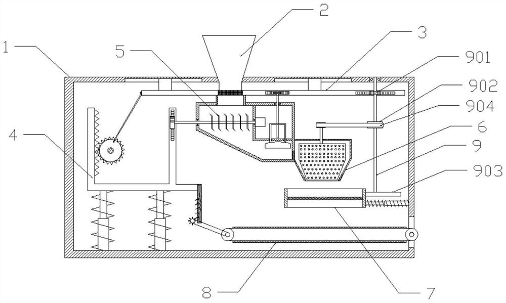
Mineral pigment grinding device for art pigment preparation
A grinding device and mineral technology, which is applied in grain processing, transportation and packaging, loading/unloading, etc., can solve the problems of poor grinding effect of the grinding device and affect the quality of the prepared pigment product, so as to improve product quality and improve the grinding effect , to avoid the effect of residual raw materials
- Summary
- Abstract
- Description
- Claims
- Application Information
AI Technical Summary
Problems solved by technology
Method used
Image
Examples
Embodiment 1
[0041] In this example, a mineral pigment milling apparatus is prepared by an art pigment, including a frame 1, a top center of the frame 1, and a feed mechanism 3 in the top of the lumen of the roser 1, and a stencil 1 The inner cavity is provided with a transmission mechanism 4, and a pulverizing mechanism 5 is provided in the inner cavity of the frame 1. The right end of the pulverizing mechanism 5 is connected to the grinding mechanism 6, and the grinding mechanism 6 is provided with a screening mechanism 7, sieve material. A discharge mechanism 8 is provided below the mechanism 7, and the discharge mechanism 8 is reached out of the frame 1.
[0042] The method of using the mineral pigment grinding device for the art pigment is specifically:
[0043] S1, place the frame 1 horizontally in the ground, and introduce the mineral pigment into the feed fighteit 2;
[0044] S2, the intermittent feed of the mineral pigment is performed by the winder 3.
[0045] S3, pulverizing the min...
Embodiment 2
[0049] On the basis of the first example, the strobe mechanism 3 includes a slider 301, a slider 302, a tape sheet 303, a first rack 304, a second rack 305, a moving rod 306, a straight gear 307, and a rotating shaft 308. The upper end of the lumen of the frame 1 is opened with the slide of the slider 302, and the lower end of the slider 302 is fixed, and the tab 303 is located in the middle of the slider 301, the upper end of the tab 303 fitting the feed strip 2 bottom The first rack 304 and the second rack 305 are connected to the front end of the slider 301, and the second rack 305 is located on the right side of the first rack 304, the right end of the movable rod 306, the right end, the movable rod 306, the left end hinged connection connection straight gear The front end surface of the 307, the first axis 308 is connected at the center of the straight gear 307, and the first rotating shaft 308 is rotatably connected to the connecting frame 1.
[0050] The transmission 4 incl...
Embodiment 3
[0056] Based on the second embodiment, the polishing mechanism 6 includes a grinding housing 601, the top of the abrasive housing 601, and the bottom of the abrasive housing 601 are opened at the bottom of the abrasive housing 602, the abrasive housing 601. The top center is rotated at the center of the second axis 603, and the top of the second shaft 603 is connected to the first pulley 604, and the second rotating shaft 603 extends to the end of the abrasive housing 601 connected to the abrasive roller 605, the abrasive roller 605. The surface is allished with wear-resistant blocks 606.
[0057] The screening mechanism 7 includes a receiving frame 701 that is located directly below the unloading port 602, and the inside of the receiving frame 701 is connected to the second filter 702, and the right side wall of the receiving frame 701 and the frame 1 The outer sleeve of the second stretch rod 703, the second stretch rod 703 is provided with a tension spring 704, and both ends of...
PUM
 Abstract
Description
Claims
Application Information
 - R&D
- Intellectual Property
- Life Sciences
- Materials
- Tech Scout
- Unparalleled Data Quality
- Higher Quality Content
- 60% Fewer Hallucinations
Browse by: Latest US Patents, China's latest patents, Technical Efficacy Thesaurus, Application Domain, Technology Topic, Popular Technical Reports.
© 2025 PatSnap. All rights reserved.Legal|Privacy policy|Modern Slavery Act Transparency Statement|Sitemap|About US| Contact US: help@patsnap.com


