
Fan electric variable-pitch motor drive control system

A technology of motor drive control and variable pitch, which is applied in the direction of motor generator control, motor control, AC motor control, etc., and can solve the problems of motor speed chattering, robustness inferior to sliding mode control method, and different speed regulation performance

Active Publication Date: 2020-12-11
HUNAN UNIV OF TECH
View PDF4 Cites 2 Cited by
  • Summary
  • Abstract
  • Description
  • Claims
  • Application Information

AI Technical Summary

Problems solved by technology

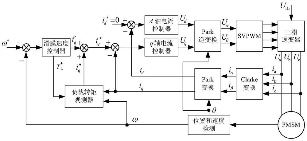
Due to the randomness of wind speed and the influence of aerodynamic effects, the motor drive control system for variable pitch of wind turbines is a multivariable strongly nonlinear uncertain system with large load inertia and fast torque changes, and the pitch required at different wind speeds and wind directions The angular speed regulation performance is different; the parameters of the traditional wind turbine pitch angle PI controller are fixed, and the robustness is not as good as the sliding mode control method, but the sliding mode control method will cause the motor speed to change when load disturbance or internal parameter perturbation occurs. obvious chattering

Method used


Image

  • Fan electric variable-pitch motor drive control system
  • Fan electric variable-pitch motor drive control system
  • Fan electric variable-pitch motor drive control system

Examples


Embodiment 1

[0113] In formula (17), is the observed value of the load torque, is the rotor angular velocity estimate, g is the feedback gain of the load torque observer, k g is the sliding mode gain of the load torque observer embodiment 1, and the load torque observer embodiment 1 is a sliding mode observer. Compared with the load torque, the motor friction has a small proportion, so that B=0, ignoring the influence of friction, then the load torque observer embodiment 1 of formula (17) becomes:

[0114]

[0115] According to (16) and formula (18) when B=0, obtain the error equation of load torque observer embodiment 1 as:

[0116]

[0117] In formula (19), is the rotor angular velocity estimation error, Observing the error for the load torque, and defining the sliding surface of the observer as According to the sliding mode accessibility condition, the stability condition of the observer system in equation (18) is k g ≤-|e 2 / J|, and g<0.

Embodiment 2

[0120] Compared with the load torque, the motor friction has a small proportion, so that B=0, ignoring the influence of friction, then the load torque observer embodiment 2 of formula (20) becomes:

[0121]

[0122] In formula (20), (21), is the observed value of the load torque, is the rotor angular velocity estimate, g is the feedback gain of the load torque observer, k W is the proportional gain of the load torque observer embodiment 2, and the load torque observer embodiment 2 is a state observer. According to the formula (16) and formula (21) when B=0, the error equation of the load torque observer embodiment 2 is obtained as:

[0123]

[0124] In formula (22), is the rotor angular velocity estimation error, is the load torque observation error. The state observer in (21) is an autonomous linear system, at k W <0, and g<0, the observer is asymptotically stable. The formula (17) of the load torque observer embodiment 1 and the formula (20) of the load to...


PUM


Abstract

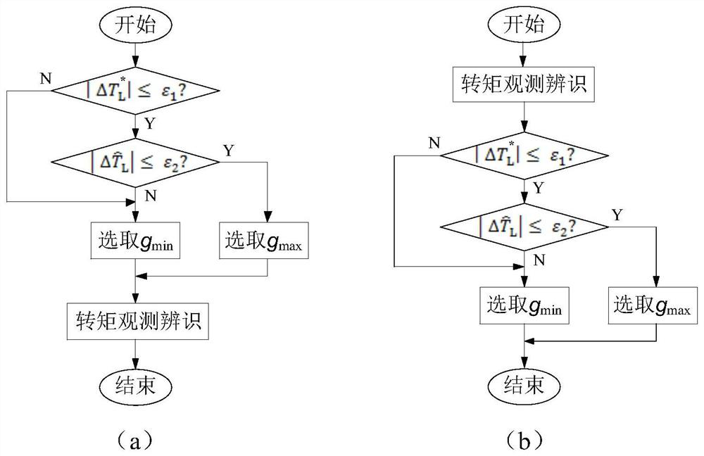
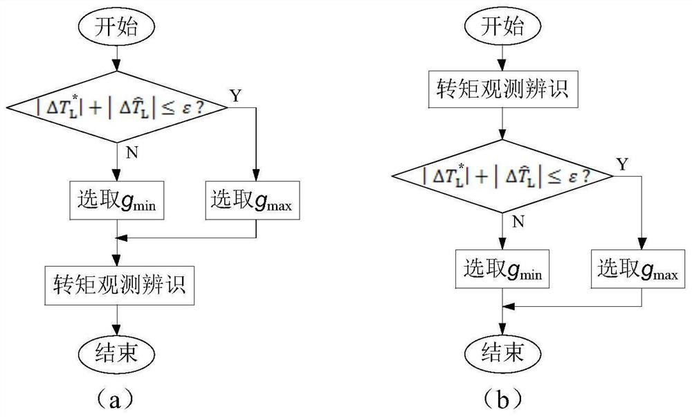
The invention discloses a fan electric variable-pitch motor drive control system.. A variable-pitch motor is a permanent magnet synchronous motor, the motor speed adopts an integral sliding mode control mode, the feedback gain of a load torque observer is automatically adjusted according to the variation of a load torque given value, and when the system speed is changed or parameters are changed,the load is disturbed to cause the change of the load torque given value or / and the change of a load torque observed value, the observation error of the load torque is quickly reduced, and the load torque observed value is fed forward and compensated to the given value of the current regulator, so that the buffeting of the system is effectively weakened, the dynamic response speed is high, the robustness is high, and the control precision of the motor speed is improved.

Description

technical field [0001] The present invention relates to the technical field of permanent magnet synchronous motors, and more specifically, relates to a drive control system for electric pitch-variable motors of fans. Background technique [0002] Permanent magnet synchronous motors have the advantages of high efficiency, large torque, and good speed performance, and are widely used in manufacturing, electric vehicles, industrial production and other fields. Due to the randomness of wind speed and the influence of aerodynamic effects, the motor drive control system for fan variable pitch is a multivariable strongly nonlinear uncertain system with large load inertia and fast torque changes, and the required pitch at different wind speeds and wind directions The angular speed regulation performance is different; the parameters of the traditional wind turbine pitch angle PI controller are fixed, and the robustness is not as good as the sliding mode control method, but the slidin...

Claims


Application Information

Patent Timeline
IPC IPC(8): H02P21/00H02P21/05H02P21/13H02P21/20H02P25/022F03D7/02F03D7/04
CPCH02P21/13H02P21/14H02P21/18H02P21/22H02P21/001H02P21/20H02P21/05H02P2101/15H02P2103/20Y02T10/64
Inventor 凌云秦斌王欣周建华黄云章汤彩珍
Owner HUNAN UNIV OF TECH
Learn More