
Switching reactor with novel coil structure

A reactor and coil technology, applied in the direction of transformer/inductor coil/winding/connection, etc., can solve the problem of excessive voltage deviation at the tap position, exceeding the standard required value, etc., to improve the accuracy of voltage regulation and meet performance requirements , the effect of reducing the distance

Pending Publication Date: 2020-12-11
TBEA SHENYANG TRANSFORMER GRP CO LTD +1
View PDF6 Cites 2 Cited by
  • Summary
  • Abstract
  • Description
  • Claims
  • Application Information

AI Technical Summary

Problems solved by technology

[0003] In view of the above problems, the purpose of the present invention is to provide a switching reactor with a new coil structure, so as to solve the problem that the voltage deviation of the corresponding tap position is too large and exceeds the required value of the standard in the bridging state of the conventional switching reactor structure

Method used


Image

  • Switching reactor with novel coil structure
  • Switching reactor with novel coil structure
  • Switching reactor with novel coil structure

Examples


Embodiment Construction

[0021] In order to make the object, technical solution and advantages of the present invention clearer, the present invention will be described in detail below in conjunction with the accompanying drawings and specific embodiments.

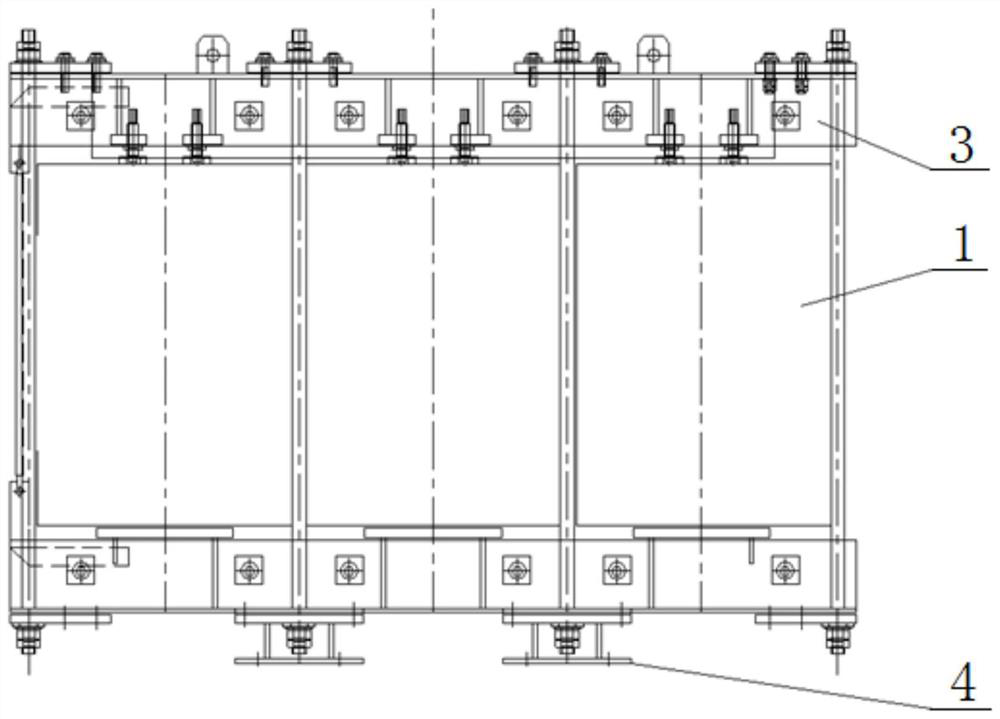
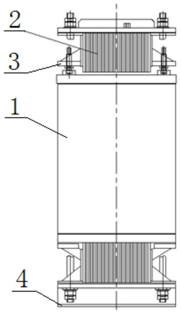
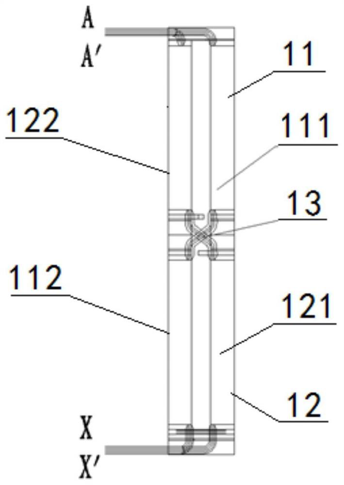
[0022] Such as Figure 1-3 As shown, a switching reactor with a novel coil structure provided by the present invention includes a double-arm coil 1, an iron core part 2 and an iron core clip 3. The iron core part 2 is a three-phase three-column structure, and each phase core A double-arm coil 1 is sleeved on the top, and the double-arm coil 1 includes a first arm coil 11 and a second arm coil 12, and the first arm coil 11 and the second arm coil 12 are wound on the core column in opposite directions to form a first The arm inner layer coil 111 and the second arm inner layer coil 121, the first arm coil 11 and the second arm coil 12 are cross-transposed at the middle position in the height of the core column and raised to the outer layer for windin...


PUM


Abstract

The invention belongs to the technical field of manufacturing of transformer products, and particularly relates to a switching reactor with a novel coil structure. The switching reactor comprises a double-arm coil, an iron core part and an iron core clamping part, wherein the iron core part is of a three-phase three-column structure, and the core column of each phase is sleeved with the double-armcoil; the double-arm coil comprises a first arm coil body and a second arm coil body, and the first arm coil body and the second arm coil body are oppositely wound on the core column to form a firstarm inner layer coil body and a second arm inner layer coil body respectively; the first arm coil and the second arm coil are crossed and transposed in the middle of the core column in the height direction to rise to the outer layer to be wound to form a first arm outer-layer coil and a second arm outer-layer coil. By adopting a crossed coil distribution structure, the two arm coils of the switching reactor are completely symmetrical in structural space and magnetic field space positions, and the distance between the two arm coils is reduced as much as possible on the premise that the two armcoils meet the insulation requirement, so that the magnetic coupling performance of the two arm coils is improved, and the performance requirements of the switching reactor in a non-bridging state anda bridging state are met.

Description

technical field [0001] The invention belongs to the technical field of manufacturing transformer products, in particular to a switching reactor with a novel coil structure. Background technique [0002] Switched reactor is a device used in reactive switching voltage regulation. Usually, the two-arm coils of switched reactors adopt a double U-shaped structure or an axial arrangement structure. This type of coil type operates in a non-bridge state However, due to the poor magnetic coupling of the coils of this type of switching reactor, the switching reactor cannot achieve the effect of minimizing the voltage division of the two-arm coils in the bridging state, making the voltage regulation There is a big difference in precision performance. Contents of the invention [0003] In view of the above problems, the purpose of the present invention is to provide a switched reactor with a new coil structure to solve the problem that the voltage deviation of the corresponding tap p...

Claims


Application Information

Patent Timeline
Patent Type & Authority Applications(China)
IPC IPC(8): H01F27/28
CPCH01F27/28
Inventor 薛雷裴红男刘均菲彭博
Owner TBEA SHENYANG TRANSFORMER GRP CO LTD
Learn More