Eureka AIR delivers breakthrough ideas for toughest innovation challenges, trusted by R&D personnel around the world.

A pressurized solar water heater system and its installation process

A solar water heater, pressure-bearing technology, applied to solar heating systems, solar collector sealing devices, solar collectors, etc., can solve the problems of inconvenient installation and disassembly, easy internal scaling, damage, etc., to improve convection exchange Effects of thermal efficiency, avoidance of structural strength, and improvement of structural strength

Active Publication Date: 2022-02-15
JIANGSU YUPU SOLAR ENERGY
View PDF6 Cites 0 Cited by
  • Summary
  • Abstract
  • Description
  • Claims
  • Application Information

AI Technical Summary

Problems solved by technology

[0003] In order to ensure the service life of the pressure-bearing solar water heater heat exchange tank, the heat exchange tank needs to be strong in pressure. The traditional heat exchange tank is a cylindrical structure. In order to ensure its strong pressure resistance, the wall of the inner tank is thicker, and the inner tank Convective heat transfer efficiency is low
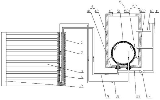
In the patent No. 200810196064.8 pressurized solar water heater, it is proposed that the bottom surface of the inner tank (that is, the upper surface of the heat transfer tank) is designed as a convex spherical tank, and the heat transfer tank is fixed on the bottom of the inner tank of the water storage tank by welding. Although the structure improves the convective heat transfer efficiency inside the inner tank and increases the average water temperature inside the inner tank; but there are the following defects: 1. The upper surface of the heat transfer tank (the heat transfer cavity in this comparative patent) is convex spherical pot shape, There is a cylindrical section extending from the lower end, and the heat exchange chamber is connected to the U-shaped tube in the heat collecting header to realize circulation. The hot water floats up to realize the convective heat exchange cycle between the heat exchange chamber and the U-shaped tube. However, the hot water in the heat exchange tank has a smaller specific gravity and lower density than cold water, and is squeezed to the inner wall of the heat exchange tank. The shape of the surface, side and bottom is inconsistent, and the force is uneven, which affects the uniformity of the temperature inside the heat exchange tank; 2. The connection between the heat exchange tank and the water storage tank is fixed by welding. This fixing method is extremely inconvenient to install. The most important thing is that the thermal stress inside the heat exchange tank is concentrated during welding, and the hot and cold water circulates continuously inside the heat exchange tank. The cold water in the water storage tank outside the heat exchange tank drops and contacts the surface of the heat exchange tank, and the temperature difference between the inside and outside of the heat exchange tank is large. The thermal stress is further concentrated, so the heat exchange tank with this structure will produce stress corrosion cracks, and serious damage will occur. Secondly, the way of welding and fixing has the disadvantage of inconvenient installation and disassembly, especially for the structure of the heat exchange tank. It is very easy to foul inside, which will affect the heating efficiency and the health of use

Method used


Image

  • A pressurized solar water heater system and its installation process
  • A pressurized solar water heater system and its installation process
  • A pressurized solar water heater system and its installation process

Examples


Embodiment Construction

[0031] In order to deepen the understanding of the present invention, the present invention will be further described below in conjunction with the embodiments and accompanying drawings. The embodiments are only used to explain the present invention and do not constitute a limitation to the protection scope of the present invention.

[0032] In the description of the present invention, it should be understood that the terms indicating orientation or positional relationship, such as based on the orientation or positional relationship shown in the drawings, are only for the convenience of describing the present invention and simplifying the description, rather than indicating or implying the Structures or units must have a specific orientation and thus should not be construed as limiting the invention.

[0033] In the present invention, unless otherwise clearly specified and limited, terms such as "connected", "provided" and "had" should be understood in a broad sense, for exampl...


PUM


Abstract

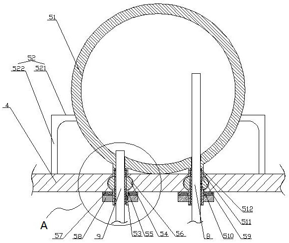
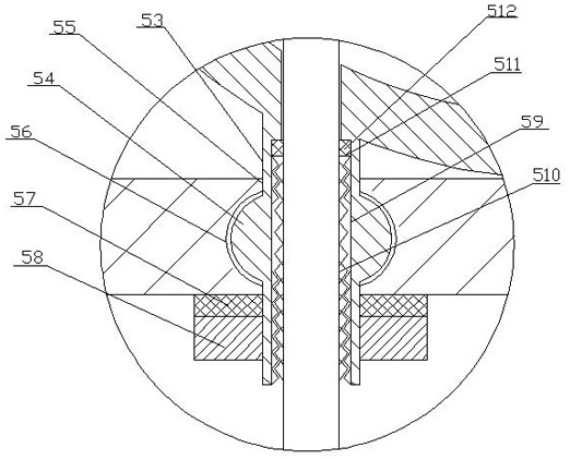
The invention relates to a pressurized solar water heater system and its installation process, which includes a heat collecting header, a support, and a plurality of heat collecting vacuum tubes placed between the heat collecting header and the support, and also includes a water storage tank and a water storage tank. The heat exchange tube inside, the heat exchange tube is placed at the bottom of the water storage tank, one end of the heat collection vacuum tube is sealed with a heat collection copper core, and the heat collection copper core extends into the heat collection header, and the heat collection header is equipped with a U-shaped The two ends of the U-shaped tube extend out of the heat collecting header and are connected with the first circulation pipe and the second circulation pipe correspondingly. The first circulation pipe and the second circulation pipe are connected with the water storage tank and communicate with the heat exchange tank; the present invention The utility model has the following advantages: while ensuring the convective heat transfer efficiency in the water storage tank, the structural strength of the heat transfer tank is improved.

Description

Technical field: [0001] The invention belongs to the field of pressurized solar heat collectors, and in particular relates to a pressurized solar water heater system and an installation process thereof. Background technique: [0002] The pressurized solar water heater has the advantages of unlimited installation position and high water outlet pressure. The heat exchange tank of the pressurized solar water heater is coupled with the solar heat collection vacuum tube through the heat exchange structure. Since the inner tank is not connected with the solar heat collection The vacuum tube is directly connected, so the inner tank has internal pressure, which is convenient for outputting powerful water flow and realizing the advantage of high water outlet pressure. [0003] In order to ensure the service life of the pressure-bearing solar water heater heat exchange tank, the heat exchange tank needs to be strong in pressure. The traditional heat exchange tank is a cylindrical stru...

Claims


Application Information

Patent Timeline
Patent Type & Authority Patents(China)
IPC IPC(8): F24S10/30F24S10/40F24S10/70F24S70/12F24S80/00F24S80/30F24S80/60F24S80/70
CPCF24S10/30F24S80/00F24S80/70F24S10/45F24S10/742F24S80/60F24S70/12F24S80/30Y02E10/44
Inventor 侯亚平范存燕陈华
Owner JIANGSU YUPU SOLAR ENERGY
Why Eureka
Eureka Blog
Learn More