
A vibration buffer limit device

A technology of limit device and limit hole, which is applied in the direction of non-rotational vibration suppression, brake type, mechanical equipment, etc., can solve the problems of lack of protection, buffer device can not limit and adjust, etc., and achieve large operation and maintenance space , stable vibration and simple structure

Active Publication Date: 2021-11-16
HENGYANG RAMON SCI & TECH CO LTD
View PDF14 Cites 0 Cited by
  • Summary
  • Abstract
  • Description
  • Claims
  • Application Information

AI Technical Summary

Problems solved by technology

[0003] The technical problem to be solved by the present invention is that the buffer device cannot be limited and adjusted during operation, nor can it play a protective role. In order to solve this problem, the present invention provides a vibration buffer limit device, which can make the buffer device work Can limit and adjust during operation, and play a protective role

Method used


Image

  • A vibration buffer limit device
  • A vibration buffer limit device
  • A vibration buffer limit device

Examples


Embodiment Construction

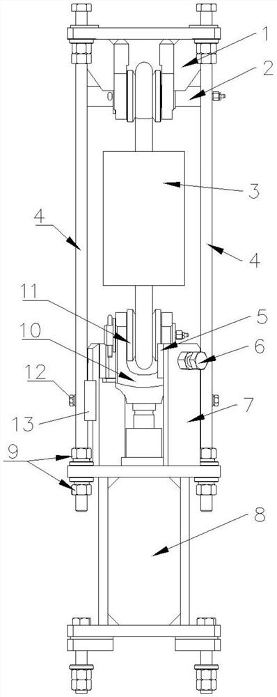
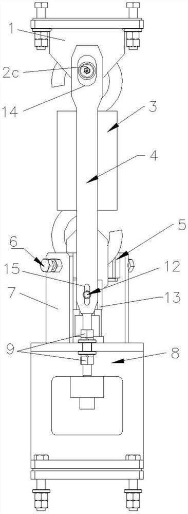
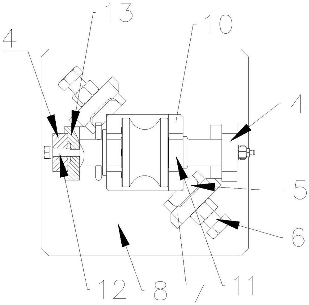
[0021] as attached Figure 1-5 As shown, a vibration buffer limit device includes a buffer connection frame 1 and a buffer connection seat 8, an upper roller assembly 2 is arranged on the lower part of the buffer connection frame 1, a roller mounting frame 10 is arranged on the upper part of the buffer connection seat 8, and a roller mounting frame 10 is arranged on The lower roller assembly 11, the two sides between the buffer connection frame 1 and the buffer connection seat 8 are respectively provided with vertical limiting plates 4, the upper part of the limiting plate 4 is provided with a vertical first limiting hole 14, and the upper roller assembly 2 has The upper roller 2a and the upper roller shaft 2c, the two ends of the upper roller shaft 2c are respectively located in the corresponding first limit hole 14 and can move up and down along the first limit hole 14, the lower roller assembly 11 has a lower roller, an upper roller 2a A bumper 3 is set between the lower ro...


PUM


Abstract

The invention relates to the field of continuous casting machines in the metallurgical industry, in particular to a vibration buffer limit device, which includes a buffer connection frame and a buffer connection seat, an upper roller assembly is arranged on the lower part of the buffer connection frame, a roller mounting frame is arranged on the upper part of the buffer connection seat, and the roller is installed The lower roller assembly is arranged on the frame, the two sides between the buffer connection frame and the buffer connection seat are respectively provided with vertical limit plates, the upper part of the limit plate is provided with a vertical first limit hole, and the upper roller assembly has an upper roller and an upper roller. The roller shaft, the lower roller assembly has a lower roller, and a buffer is arranged between the upper roller and the lower roller. The present invention, through the first limit hole opened on the limit plate, can limit the stroke of the upper roller shaft when the buffer is forced to reciprocate, thereby limiting the position of the reciprocating motion of the buffer, and can give the vibration device It plays the role of limit protection, so as to avoid accidents such as downtime caused by the over-travel operation of the buffer.

Description

technical field [0001] The invention relates to the field of continuous casting machines in the metallurgical industry, in particular to a vibration buffering and limiting device. Background technique [0002] Continuous casting is continuous steel casting, which is an important process for steel plants to produce various steel products. The crystallizer is the core component of continuous casting production equipment. The crystallizer vibrates under the drive of the vibrating device to help condense into a billet with a solid shell Pull it out from below more smoothly. The electric cylinder or driver drives the vibrating device to vibrate. There is a buffer device on the vibrating arm to balance the weight of the mold and reduce the impact of the vibration load on the vibrating device. The vibrating device plays a vital role in the vibration of the entire vibrating frame and the crystallizer. It plays an important role and directly affects the process of billet production ...

Claims


Application Information

Patent Timeline
Patent Type & Authority Patents(China)
IPC IPC(8): F16F15/02F16D71/00
CPCF16D71/00F16F15/02
Inventor 田陆戴勇雄欧阳云云卢红山刘云何文明江雨津
Owner HENGYANG RAMON SCI & TECH CO LTD
Learn More