Broadband low-profile 4X4 array dual-polarization directional antenna

A directional antenna, low profile technology, applied in antennas, antenna coupling, antenna arrays and other directions, can solve the problem of unable to meet the requirements of 20dB isolation, unable to guarantee cross-polarization, insufficient antenna bandwidth, etc., to achieve good market prospects, consistent High performance and general purpose

Pending Publication Date: 2020-12-08
上海增信电子有限公司
View PDF0 Cites 3 Cited by
  • Summary
  • Abstract
  • Description
  • Claims
  • Application Information

AI Technical Summary

Problems solved by technology

[0004] The purpose of the present invention is to provide a dual-polarized directional antenna with a broadband low-profile 4X4 array, which solves the problem that the antenna bandwidth is not enough to cover the entire bandwidth of 5.15GHz to 5.85GHz, and due to the relationship of in-phase feed, the isolation between the two ports The isolation degree is often only about 15dB, which cannot meet the 20dB isolation requirement required by the system, nor can it guarantee the technical problem that the cross-polarization ratio reaches the requirement of more than 15dB.

Method used


Image

  • Broadband low-profile 4X4 array dual-polarization directional antenna
  • Broadband low-profile 4X4 array dual-polarization directional antenna
  • Broadband low-profile 4X4 array dual-polarization directional antenna

Examples


Embodiment Construction

[0019] The following will clearly and completely describe the technical solutions in the embodiments of the present invention with reference to the accompanying drawings in the embodiments of the present invention. Obviously, the described embodiments are only some, not all, embodiments of the present invention. Based on the embodiments of the present invention, all other embodiments obtained by persons of ordinary skill in the art without making creative efforts belong to the protection scope of the present invention.

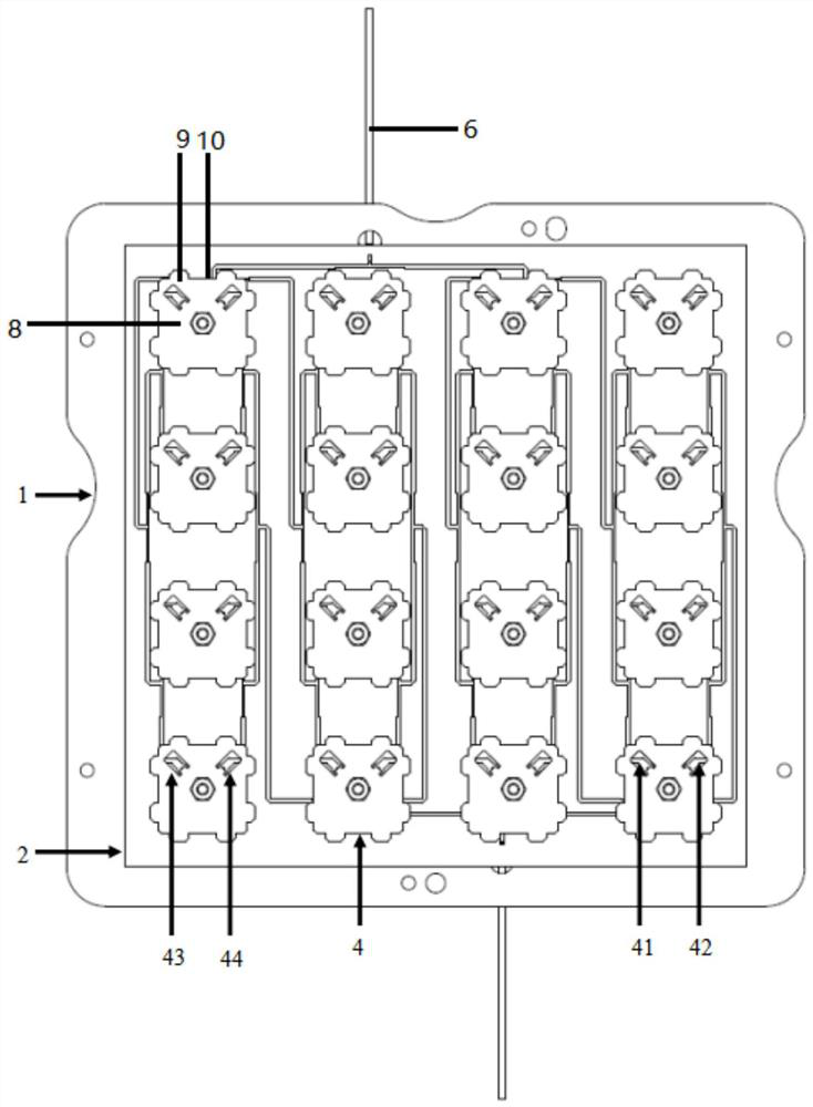
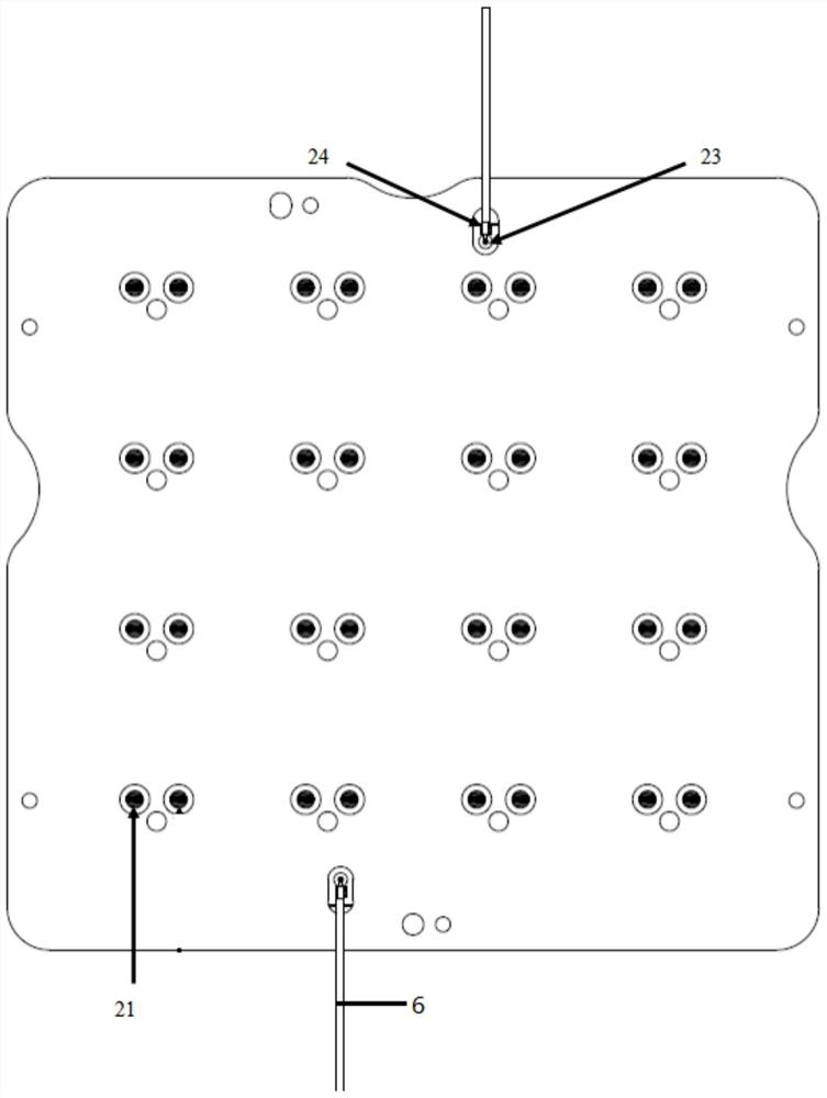
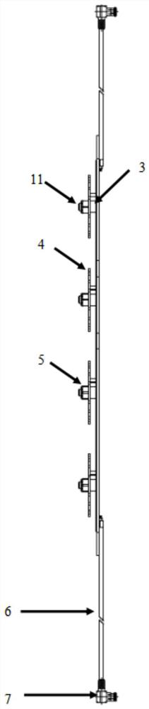
[0020] see Figure 1-3 , the present invention provides a technical solution: a broadband low-profile 4X4 array dual-polarization directional antenna, including an antenna body, and the antenna body includes a reflector 1, a high-frequency dielectric substrate 2, a circular pad column 3, a radiation unit 4, and a nut 5. The coaxial cable 6 and the radio frequency connector 7, the high-frequency dielectric substrate 2 are installed in the middle directly above ...


PUM


Abstract

The invention discloses a broadband low-profile 4X4 array dual-polarization directional antenna which comprises an antenna body, the antenna body comprises a reflecting plate, a high-frequency dielectric substrate, a circular cushion column, a radiation unit, a nut, a coaxial cable and a radio frequency connector, and the high-frequency dielectric substrate is installed in the middle over the reflecting plate. A plurality of groups of circular cushion columns are uniformly mounted at the joint of the high-frequency dielectric substrate and the reflecting plate; a plurality of groups of radiation units are uniformly arranged on the circular cushion columns; studs are inserted in the connecting positions of the radiation units and the circular cushion columns in a penetrating mode; nuts arefixed on the studs in a threaded manner and are in contact with the radiation units; The central current zero point of the radiation unit is in short circuit with the reflecting plate, and the surfaceof the radiation unit is symmetrically provided with a first window and a second window. According to the invention, the antenna radiation unit is optimally designed, and a circular or square radiation patch different from the traditional radiation patch is adopted, so that the antenna has the advantages of wide frequency band, high isolation, high cross polarization ratio and low profile.

Description

technical field [0001] The invention relates to the technical field of directional antennas, in particular to a broadband low-profile 4X4 array dual-polarization directional antenna. Background technique [0002] Directional antenna refers to an antenna that transmits and receives electromagnetic waves particularly strongly in one or several specific directions, while transmitting and receiving electromagnetic waves in other directions is zero or extremely small. The purpose of using directional transmitting antennas is to increase the effective utilization of radiation power and increase confidentiality; the main purpose of using directional receiving antennas is to enhance signal strength and increase anti-interference capabilities, including dual-polarized directional antennas. Currently, the demand for directional data transmission Therefore, higher requirements are put forward for the antenna's gain, lobe width, isolation, cross-polarization ratio and other indicators. ...

Claims


Application Information

Patent Timeline
Patent Type & Authority Applications(China)
IPC IPC(8): H01Q1/52H01Q1/12H01Q1/36H01Q1/48H01Q1/50H01Q15/24H01Q19/10H01Q21/00H01Q21/06
CPCH01Q1/12H01Q1/36H01Q1/48H01Q1/50H01Q1/523H01Q15/24H01Q19/10H01Q21/0006H01Q21/061
Inventor 汪卫
Owner 上海增信电子有限公司
Why Eureka
Try Eureka