
Display panel and forming method thereof

A technology for display panels and display areas, applied in electrical components, electrical solid-state devices, circuits, etc., and can solve problems such as peeling off of flattened dielectric layers

Inactive Publication Date: 2020-12-04
ZHANGJIAGANG HONGJIA DIGITAL TECH
View PDF0 Cites 0 Cited by
  • Summary
  • Abstract
  • Description
  • Claims
  • Application Information

AI Technical Summary

Problems solved by technology

However, during the use of the existing organic light-emitting diode display panel, the planarization dielectric layer is prone to peeling off. At present, in order to prevent the planarization dielectric layer from peeling off, through holes are usually provided in the interlayer insulating layer, and then the planarization dielectric layer Layers are embedded in the interlayer insulating layer, but the above-mentioned technical means cannot effectively prevent peeling off at the edges and corners of the OLED display panel

Method used


Image

  • Display panel and forming method thereof
  • Display panel and forming method thereof
  • Display panel and forming method thereof

Examples


Embodiment Construction

[0032] In order to better understand the technical solutions of the present invention, the embodiments of the present invention will be described in detail below in conjunction with the accompanying drawings.

[0033] It should be clear that the described embodiments are only some of the embodiments of the present invention, not all of them. Based on the embodiments of the present invention, all other embodiments obtained by persons of ordinary skill in the art without creative efforts fall within the protection scope of the present invention.

[0034] Terms used in the embodiments of the present invention are only for the purpose of describing specific embodiments, and are not intended to limit the present invention. As used in the embodiments of the present invention and the appended claims, the singular forms "a", "said" and "the" are also intended to include the plural forms unless the context clearly indicates otherwise.

[0035] It should be understood that the term "an...


PUM

PropertyMeasurementUnit
Concentrationaaaaaaaaaa
Diameteraaaaaaaaaa
Lengthaaaaaaaaaa

Abstract

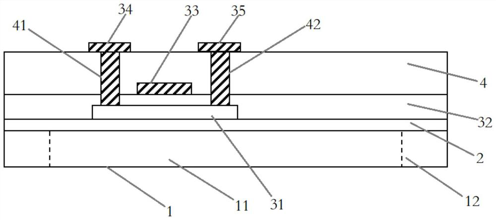
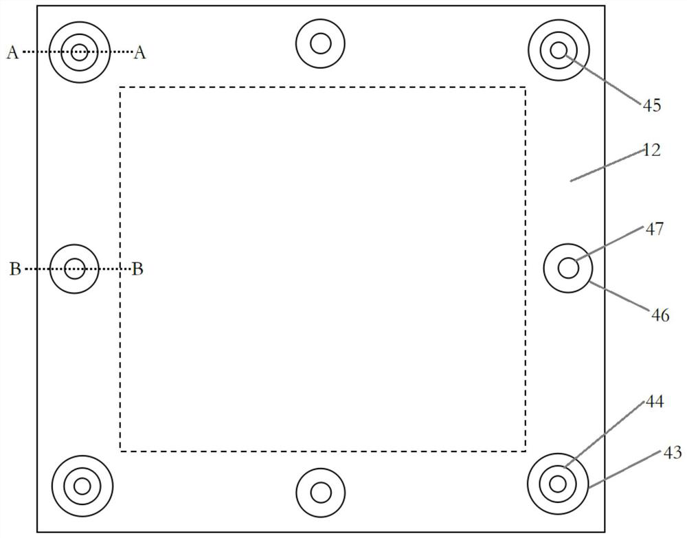
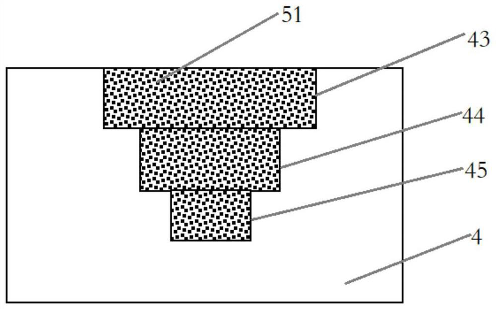
The invention relates to a display panel and a forming method thereof. The method comprises the following steps of: defining a display region and an edge non-display region surrounding the display region on a substrate; depositing a buffer layer, an active unit, a gate dielectric layer, a gate unit, a silicon dioxide interlayer, a source electrode and a drain electrode on the substrate; forming first to fifth grooves in the silicon dioxide interlayer layer at four corners of the edge non-display region and in the middle regions of the four edges respectively, and roughening the grooves; forming first, second and third SiO2 nanowires and an organic resin laminated structure; forming a first concave region and a second concave region respectively; then forming a planarization layer on the silicon dioxide interlayer, wherein a part of the planarization layer is embedded into the first concave region and the second concave region; and forming a pixel electrode which is electrically connected with a drain electrode and an organic light-emitting element on the planarization layer.

Description

technical field [0001] The present invention relates to the technical field of display panels, in particular to a display panel and a forming method thereof. Background technique [0002] Organic light-emitting diodes have the advantages of thinness and lightness, active light emission, wide viewing angle, fast response, low energy consumption, excellent low temperature and shock resistance, and potential flexible design. Organic light-emitting diodes are all solid-state devices, without vacuum chambers, and without liquid components, so they are not afraid of vibrations, easy to use, and feature high resolution, wide viewing angle, and wide operating temperature range. They will be widely used in weaponry and harsh environments. application. Among them, organic light emitting diodes are used as flat backlight sources and lighting sources in the display field, that is, organic light emitting diode display panels. However, during the use of the existing organic light-emitti...

Claims


Application Information

Patent Timeline
IPC IPC(8): H01L27/32
CPCH10K59/124H10K59/12H10K59/1201
Inventor 徐扬宋文博张雅萍
Owner ZHANGJIAGANG HONGJIA DIGITAL TECH
Learn More