
Power system of thermal self-compensation type hydrogen fuel cell power-assisted bicycle

A technology for assisting bicycles and fuel cells, which is applied in the direction of fuel cell additives, fuel cells, bicycle batteries, etc., can solve the problems of high cost of liquid hydrogen application, large hydrogen compression work, hydrogen leakage, etc., to meet the needs of economic and social markets, Effect of improving hydrogen desorption performance and reducing energy loss

Pending Publication Date: 2020-12-04
JIANGSU JICUI ANTAI CHUANGMING ADVANCED ENERGY MATERIALS RES INST CO LTD
View PDF0 Cites 1 Cited by
  • Summary
  • Abstract
  • Description
  • Claims
  • Application Information

AI Technical Summary

Problems solved by technology

High-pressure gaseous hydrogen storage is widely used, easy to operate, low in cost, and fast in charging and discharging hydrogen, but it requires heavy pressure-resistant containers, consumes a lot of hydrogen compression work, and has unsafe factors such as hydrogen leakage and container explosion.
Cryogenic liquid hydrogen storage has a wide range of applications in hydrogen refueling stations around the world, but its application in vehicle-mounted systems is immature and has potential safety hazards
In addition, limited by technology, the cost of domestic liquid hydrogen application is very high

Method used


Image

  • Power system of thermal self-compensation type hydrogen fuel cell power-assisted bicycle
  • Power system of thermal self-compensation type hydrogen fuel cell power-assisted bicycle
  • Power system of thermal self-compensation type hydrogen fuel cell power-assisted bicycle

Examples


Embodiment Construction

[0023] In order to make the object, technical solution and advantages of the present invention clearer, the implementation of the present invention and its beneficial effects will be further described in detail below in conjunction with the accompanying drawings.

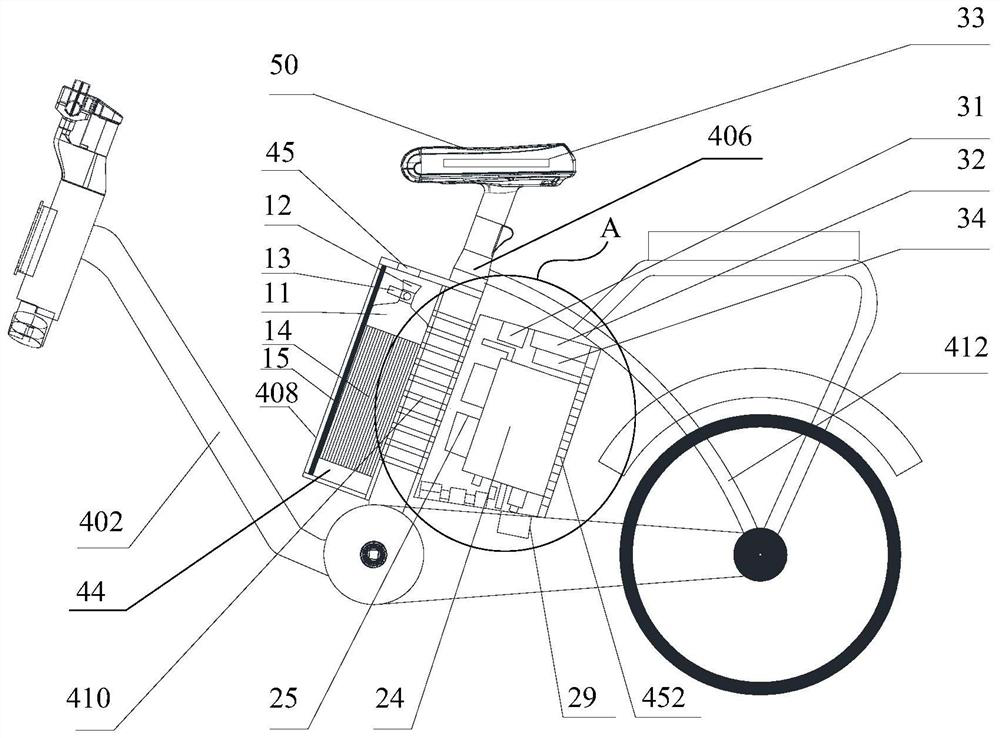
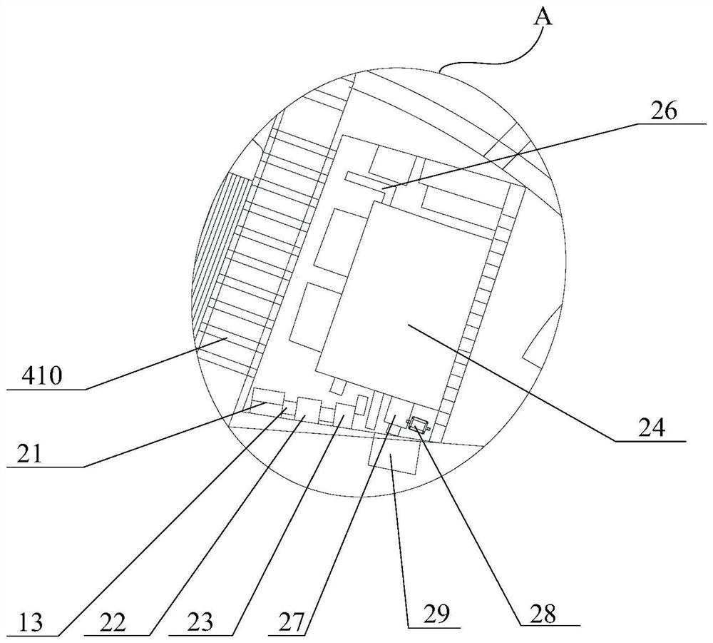
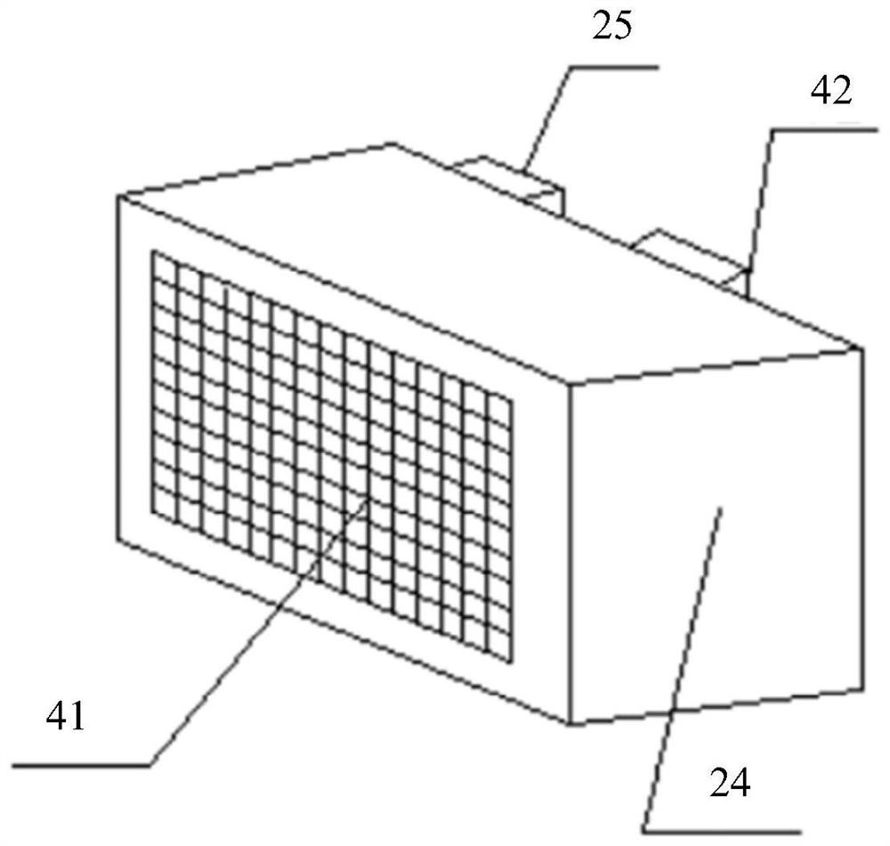
[0024] Such as Figure 1 to Figure 4 As shown, one embodiment of the present invention provides a power system of a heat self-compensating hydrogen fuel cell assisted bicycle.

[0025] The power system of the thermal self-compensating hydrogen fuel cell assisted bicycle includes a hydrogen storage tank 11, a fuel cell stack 24, a control device and a driving device. The hydrogen storage tank 11 is specifically a solid hydrogen storage alloy tank for storing and providing high-purity hydrogen. The hydrogen storage tank 11 supplies hydrogen to the fuel cell stack 24 through the hydrogen supply pipeline 13, and the fuel cell stack 24 supplies power to the hydrogen storage tank 11, the driving device and the control dev...


PUM


Abstract

The invention provides a power system of a thermal self-compensation type hydrogen fuel cell power-assisted bicycle. The power system comprises a hydrogen storage tank, a fuel cell stack, a control device and a driving device. The power-assisted bicycle is provided with a bicycle frame, and the bicycle frame specifically comprises a front oblique beam, a vertical pipe, a first shell arranged on the front side of the vertical pipe and a second shell arranged on the rear side of the vertical pipe which are connected. The interior of the first shell and the interior of the second shell are both hollow, an air outlet is formed in the first shell, an air inlet is formed in the second shell, the internal space of the first shell is connected with the internal space of the second shell through aplurality of air pipelines, a first air flow channel is formed in the first shell, and a second air flow channel is formed in the internal space of the multiple air pipelines; and the hydrogen storagetank is arranged in the first air flow channel, the fuel cell stack is arranged in the second shell, and hot air exhausted by the fuel cell stack enters the first air flow channel through the secondair flow channel and is exhausted from the air outlet after flowing through the hydrogen storage tank. Waste heat generated during operation of the fuel cell stack is utilized to realize thermal compensation.

Description

technical field [0001] The present invention relates to the technical field of power systems of electric bicycles, hydrogen storage technology and fuel cell technology. Background technique [0002] Hydrogen energy is considered to be an ideal clean energy, which has the advantages of light weight, abundant reserves, and environmental friendliness. The main industrial chain of hydrogen energy includes upstream hydrogen production, midstream hydrogen transportation and storage, downstream hydrogen refueling stations, hydrogen fuel cells and applications. Midstream hydrogen storage includes high-pressure gaseous hydrogen storage, low-temperature liquid hydrogen storage and solid-state hydrogen storage. High-pressure gaseous hydrogen storage is widely used, easy to operate, low in cost, and fast in charging and discharging hydrogen, but it requires heavy pressure-resistant containers, consumes a lot of hydrogen compression work, and has unsafe factors such as hydrogen leakage ...

Claims


Application Information

Patent Timeline
Patent Type & Authority Applications(China)
IPC IPC(8): B60L50/70B60L50/71B62J43/13B62J43/28H01M8/04082
CPCB60L50/70B60L50/71B62J43/13B62J43/20H01M8/04201Y02E60/50Y02T90/40
Inventor 原建光武英张宝阎有花周少雄
Owner JIANGSU JICUI ANTAI CHUANGMING ADVANCED ENERGY MATERIALS RES INST CO LTD
Learn More