A floor boundary detection method, device, equipment and storage medium

A boundary detection and floor technology, applied in the field of surveying and mapping, can solve problems such as inaccurate floor boundary detection results, affecting the efficiency of leveling and grinding processes, and achieve the effect of improving accuracy

Active Publication Date: 2021-02-12
GUANGDONG BOZHILIN ROBOT CO LTD
View PDF5 Cites 0 Cited by
  • Summary
  • Abstract
  • Description
  • Claims
  • Application Information

AI Technical Summary

Problems solved by technology

[0003] In the prior art, the height of the ground around the building is generally used directly as the height of the building’s reference level, and the floor boundary after the construction is completed is extracted, and the extracted area is used as the boundary of the floor, but the ground height around the building cannot accurately reflect the height of the building. The height of the base level of the object, the extracted area cannot accurately reflect the effective working area, making the floor boundary detection result inaccurate, which in turn affects the operation efficiency of the leveling process and the grinding process

Method used


Image

  • A floor boundary detection method, device, equipment and storage medium
  • A floor boundary detection method, device, equipment and storage medium
  • A floor boundary detection method, device, equipment and storage medium

Examples


Embodiment 1

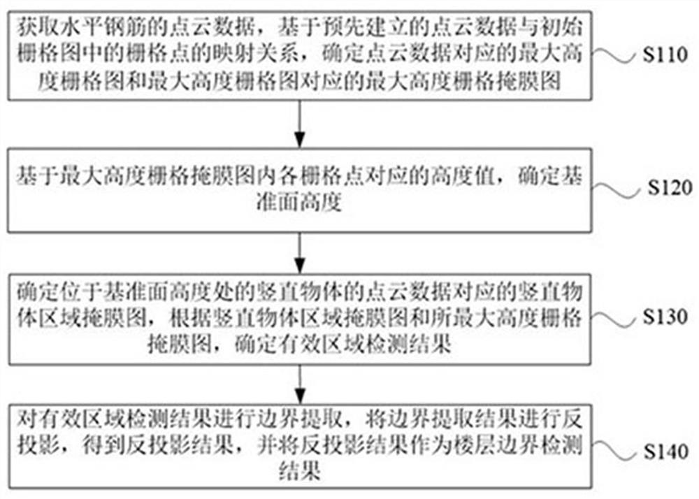
[0029] figure 1 It is a schematic flow chart of a floor boundary detection method provided by Embodiment 1 of the present invention. This embodiment can be applied to determine the effective area detection result according to the determined maximum height grid mask map and vertical object area mask map, and further according to The valid area detection result determines the status of the floor boundary detection result, and the method can be executed by a floor boundary detection device, wherein the device can be implemented by software and / or hardware, and is generally integrated in the floor boundary detection device. For details, see figure 1 As shown, the method may include the following steps:

[0030] S110. Acquire point cloud data of horizontal reinforcement, and determine the maximum height grid map corresponding to the point cloud data and the maximum height grid map corresponding to the point cloud data based on the mapping relationship between the pre-established p...

Embodiment 2

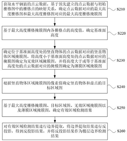
[0055] image 3 It is a schematic flowchart of a floor boundary detection method provided by Embodiment 2 of the present invention. The technical solution of this embodiment is refined in the steps of the foregoing embodiments. Optionally, the method further includes: determining the mask map corresponding to the point cloud data whose height is less than the height of the reference plane as an invalid area mask map, and determining the mask map corresponding to the point cloud data whose height is greater than or equal to the height of the reference plane The mask image corresponding to the data is determined as the thin film region mask image. Optionally, the determining the effective region detection result according to the vertical object region mask map and the maximum height grid mask map includes: determining the effective region detection result according to the pixel values ​​of the vertical object region mask map The target area map of the vertical object and the v...

Embodiment 3

[0078] Image 6 It is a schematic flowchart of a floor boundary detection method provided by Embodiment 3 of the present invention. The technical solution of this embodiment is refined in the steps of the foregoing embodiments. Optionally, the determining the height of the reference plane based on the height values ​​of each grid point in the maximum height raster mask map includes: performing region segmentation on the maximum height raster mask map to generate a maximum connected domain Detection area; arrange the grid points of the maximum connected domain detection area in the order of decreasing height value to obtain the maximum connected domain detection area set; determine the target point cloud corresponding to the grid points in the maximum connected domain detection area set data, calculating the median of the height values ​​of the target point cloud data, and using the median of the height values ​​as the height of the reference plane. For the parts not describe...


PUM


Abstract

The embodiment of the invention discloses a floor boundary detection method, device, equipment and storage medium. Obtain the point cloud data of the horizontal reinforcement, and determine the maximum height grid map and the maximum height grid mask corresponding to the maximum height grid map based on the pre-established mapping relationship between the point cloud data and the grid points in the initial grid map The film map, according to the height value corresponding to each grid point in the maximum height grid mask map, determines the height of the reference plane, and determines the vertical object area mask map corresponding to the point cloud data of the vertical object located at the height of the reference plane, The effective area is extracted according to the vertical object area mask map and the maximum height grid mask map, and the floor boundary detection result is further obtained according to the effective area detection result. The purpose of improving the accuracy of the floor boundary detection results is achieved, which is conducive to ensuring the precise operation of the robot in the leveling process and the grinding process and improving the operating efficiency.

Description

technical field [0001] Embodiments of the present invention relate to surveying and mapping technology, and in particular to a floor boundary detection method, device, equipment and storage medium. Background technique [0002] With the decline of the demographic dividend, the construction industry has put forward higher and higher requirements and demands for the automation of surveying and mapping technology. In recent years, the emergence of semi-automated self-elevating building equipment has replaced some repetitive and labor-intensive tasks. Correspondingly, the automation level of surveying and mapping technology needs to be improved accordingly. In the field of construction, the formation of floors and floors requires the execution of construction techniques such as grouting, troweling, and leveling in turn. Among them, during the troweling and leveling process of building construction equipment, it is necessary to obtain the working area information in advance, tha...

Claims


Application Information

Patent Timeline
Patent Type & Authority Patents(China)
IPC IPC(8): G06T7/11G06T7/13G06T3/00G06T7/187G06T7/62G06K9/62
CPCG06T7/11G06T7/13G06T3/005G06T7/187G06T7/62G06T2207/10028G06F18/23
Inventor 傅志刚杨海溢贾宁吴则刚周森标彭登陶永康刘玉平
Owner GUANGDONG BOZHILIN ROBOT CO LTD
Why Eureka
Try Eureka