Method for measuring surface clearance and surface difference of reflection difference workpiece

A workpiece surface and difference technology, applied in the direction of measuring devices, optical devices, instruments, etc., can solve the problems of inability to accurately obtain gap surface difference values, poor light strip collection quality, reduce equipment costs, etc., achieve short image capture time, The effect of fast adjustment speed and reduced equipment cost

Pending Publication Date: 2022-04-22
易思维(杭州)科技有限公司
View PDF0 Cites 0 Cited by
  • Summary
  • Abstract
  • Description
  • Claims
  • Application Information

AI Technical Summary

Problems solved by technology

[0003] In view of the above-mentioned problems, the present invention proposes a method for measuring the surface gap and surface difference of workpieces with reflective differences, which can effectively solve the problem that the quality of light strip collection is poor due to the reflective differences on the surface of the measured workpieces, and the gap and surface difference cannot be accurately obtained; the method It can be applied to ordinary gap and surface difference measurement equipment (ordinary camera + laser), and there is no need for additional selection to design special measurement equipment for reflective difference workpieces, which greatly reduces equipment costs

Method used


Image

  • Method for measuring surface clearance and surface difference of reflection difference workpiece
  • Method for measuring surface clearance and surface difference of reflection difference workpiece
  • Method for measuring surface clearance and surface difference of reflection difference workpiece

Examples


Embodiment Construction

[0043] The technical solutions of the present invention will be described in detail below in conjunction with the accompanying drawings and specific embodiments.

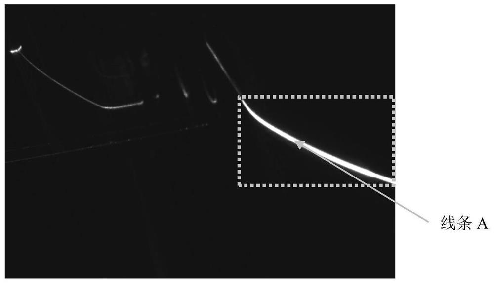
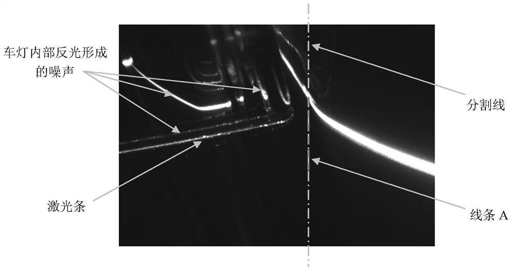
[0044] A method for measuring the surface gap and surface difference of workpieces with reflective differences. The workpieces with reflective differences include areas with different reflectivity. The surface with high reflectivity is recorded as bright surface, and the surface with low reflectivity is recorded as dark surface. gaps and / or flush features formed between them;

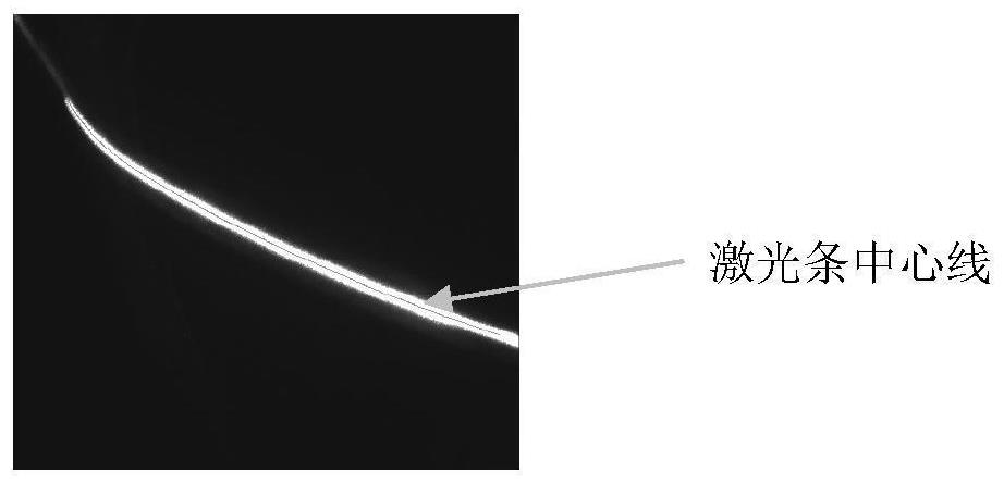
[0045]Move the measurement equipment to the vicinity of the gap and / or surface difference feature, the measurement equipment includes a camera and a line laser; the line laser projects a laser bar to the feature position, and the camera continuously collects two laser bar images; according to the laser bar on the two laser bar images The brightness is recorded as low-brightness laser bar image and high-brightness laser bar image respectively;...


PUM


Abstract

The invention discloses a method for measuring the surface clearance and surface difference of a reflection difference workpiece, the reflection difference workpiece comprises areas with different reflection rates, the surface with high reflection rate is marked as a bright surface, and the surface with low reflection rate is marked as a dark surface; the line laser projects a laser bar to the feature position, and the camera continuously collects two laser bar images; extracting a laser strip center line on the bright surface from the low-brightness laser strip image, and recording the laser strip center line as a light strip I; extracting a laser bar center line on the dark surface from the high-brightness laser bar image, and recording the laser bar center line as a light bar II; solving a gap value and / or a surface difference value by using the light bar I and the light bar II; the method can effectively solve the problems that the light strip collection quality is poor and the gap surface difference cannot be accurately obtained due to the reflection difference of the surface of the measured workpiece; the method has the characteristics of good universality, low cost, high speed and high precision.

Description

technical field [0001] The invention relates to the field of structured light measurement, in particular to a method for measuring the surface gap and surface difference of a reflective difference workpiece. Background technique [0002] In recent years, with the rapid development of photoelectric sensing technology, computer technology and optical semiconductor technology, line-structured light measurement has been widely used in the fields of industrial inspection, target recognition and reverse engineering due to its non-contact, high-efficiency and real-time measurement characteristics. Among them, the use of line structured light to measure the gap and surface difference characteristics of the product surface has gradually become the mainstream automatic detection method. The bar center extraction algorithm and the camera calibration model jointly calculate the three-dimensional coordinate information of the surface of the measured object. In this process, the shooting...

Claims


Application Information

Patent Timeline
IPC IPC(8): G01B11/14G01B11/25
CPCG01B11/14G01B11/2518
Inventor 郭寅郭磊尹仕斌冯伟昌李光辉
Owner 易思维(杭州)科技有限公司
Why Eureka
Try Eureka