Device and method for removing residual dimethomorph in ginsenoside extract
A technology of dimethomorph and ginsenoside, which is applied in the field of removal devices for dimethomorph residues in ginsenoside extracts, can solve the problems of excessive pesticide residues, increased operation difficulty, and low extraction efficiency, and achieve technical index improvement , high clarity and high removal rate of pesticide residues
- Summary
- Abstract
- Description
- Claims
- Application Information
AI Technical Summary
Problems solved by technology
Method used
Image
Examples
Embodiment 1
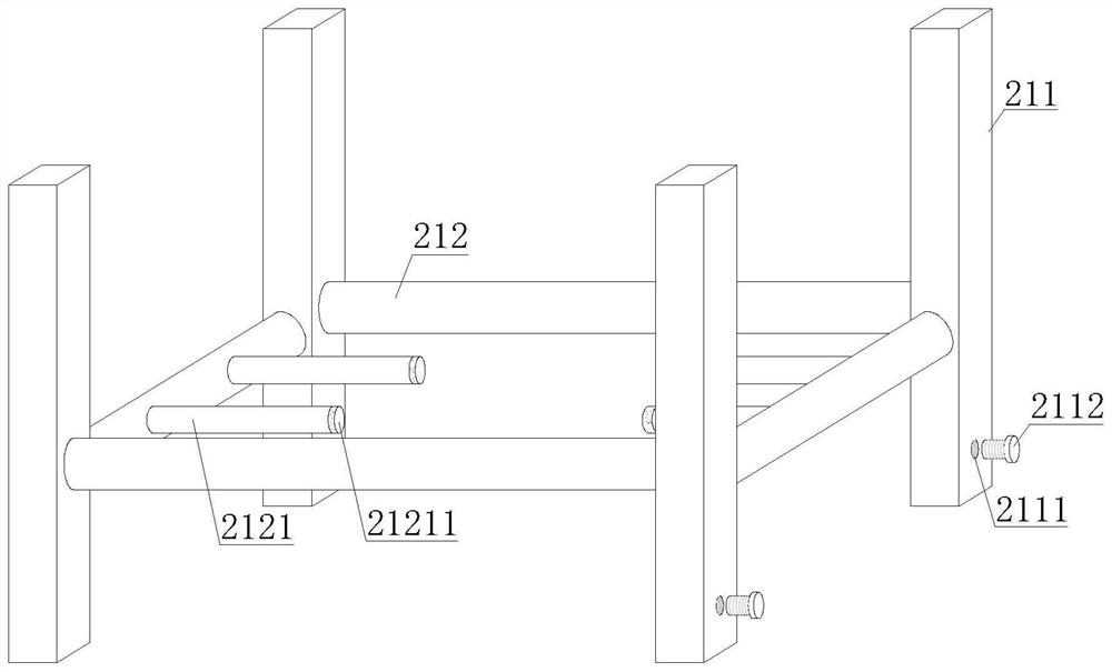
[0034] refer to Figure 1-3, a device for removing residual dimorpholine residues in ginsenoside extracts, comprising a reaction mechanism 1 and a fixing mechanism 2, the upper end of the fixing mechanism 2 is provided with a reaction mechanism 1, and the reaction mechanism 1 includes a reaction cylinder 11, a reinforcing seat 12 and The motor 13, the upper surface of the reaction cylinder 11 is fixedly equipped with a reinforcement seat 12, the upper end of the reinforcement seat 12 is provided with a motor 13, the output end of the motor 13 is connected with the reaction cylinder 11, and the lower surface of the reaction cylinder 11 is provided with a fixing mechanism 2 , the fixing mechanism 2 includes a support frame 21 and an underframe 22, the lower end of the support frame 21 is provided with an underframe 22, the support frame 21 includes a vertical support rod 211 and a horizontal fixed rod 212, and the vertical support rods 211 and the horizontal fixed rods 212 are al...
Embodiment 2
[0036] refer to figure 2 and 5 , the reaction cylinder 11 includes a liquid injection pipe 111, a connecting groove 112, a display panel 113, a magnetic hole 114, an external connection pipe 115 and a connection cylinder 116, the upper surface of the reaction cylinder 11 is provided with a liquid injection pipe 111, and the outer surface of the reaction cylinder 11 A connection groove 112 and a magnetic hole 114 are provided, a display panel 113 is fixedly installed on the outer surface of the reaction cylinder 11, an external connecting pipe 115 is provided on one side of the reaction cylinder 11, and a connection cylinder 116 is provided on the lower bottom surface of the reaction cylinder 11, note Both the liquid pipe 111 and the external connection pipe 115 are in communication with the reaction cylinder 11 .
Embodiment 3
[0038] refer to Figure 6 , the reaction cylinder 11 also includes a rotating rod 117, a heater 118, a temperature sensor 119, a pressure sensor 11A, a first electric door 11B and a second electric door 11C, the inside of the reaction cylinder 11 is provided with a rotating rod 117, and the rotating rod 117 One end of one end passes through reinforcing seat 12 and is connected with the output end of motor 13, heater 118, temperature sensor 119 and pressure sensor 11A are all fixedly installed on the inner wall of reaction cylinder 11, heater 118, temperature sensor 119 and pressure The sensors 11A are electrically connected to the external power supply, and the temperature sensor 119 and the pressure sensor 11A are connected to the display panel 113 for signals. The inside of the reaction cylinder 11 is provided with a first electric door 11B and a second electric door 11C. The first electric door Both ends of 11B and the second electric door 11C are fixedly installed on the i...
PUM
 Abstract
Description
Claims
Application Information
 - R&D
- Intellectual Property
- Life Sciences
- Materials
- Tech Scout
- Unparalleled Data Quality
- Higher Quality Content
- 60% Fewer Hallucinations
Browse by: Latest US Patents, China's latest patents, Technical Efficacy Thesaurus, Application Domain, Technology Topic, Popular Technical Reports.
© 2025 PatSnap. All rights reserved.Legal|Privacy policy|Modern Slavery Act Transparency Statement|Sitemap|About US| Contact US: help@patsnap.com


