Radar sensor and method for operating a radar sensor

Active Publication Date: 2015-01-01
ROBERT BOSCH GMBH
View PDF6 Cites 20 Cited by
  • Summary
  • Abstract
  • Description
  • Claims
  • Application Information

AI Technical Summary

Benefits of technology

This invention is about improving the performance of radar systems by combining information from multiple ramp sets. This helps to achieve clearer and more accurate radar detection, even at low sampling rates and with a small number of ramps. The method also allows for efficient processing of the detected signals by adjusting the sampling frequency based on the ramp period. This helps to increase the efficiency of the radar system and makes it more cost-effective for use in vehicles. Additionally, the invention allows for the extended range of unambiguousness for the radar sensor, making it more reliable and accurate.

Problems solved by technology

For example, such driver assistance systems may inform the vehicle driver about an obstacle while parking.
In short, the system requirements with respect to the unambiguousness and the separability are limited by the requirements on the hardware, for example, the sampling rate, memory capacity, data transmission rate, and computing complexity.

Method used


Image

  • Radar sensor and method for operating a radar sensor
  • Radar sensor and method for operating a radar sensor
  • Radar sensor and method for operating a radar sensor

Examples


Embodiment Construction

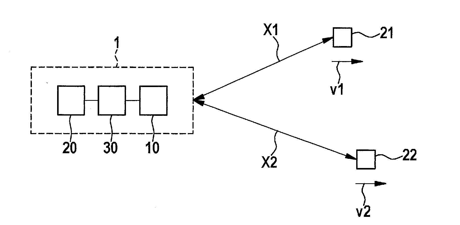
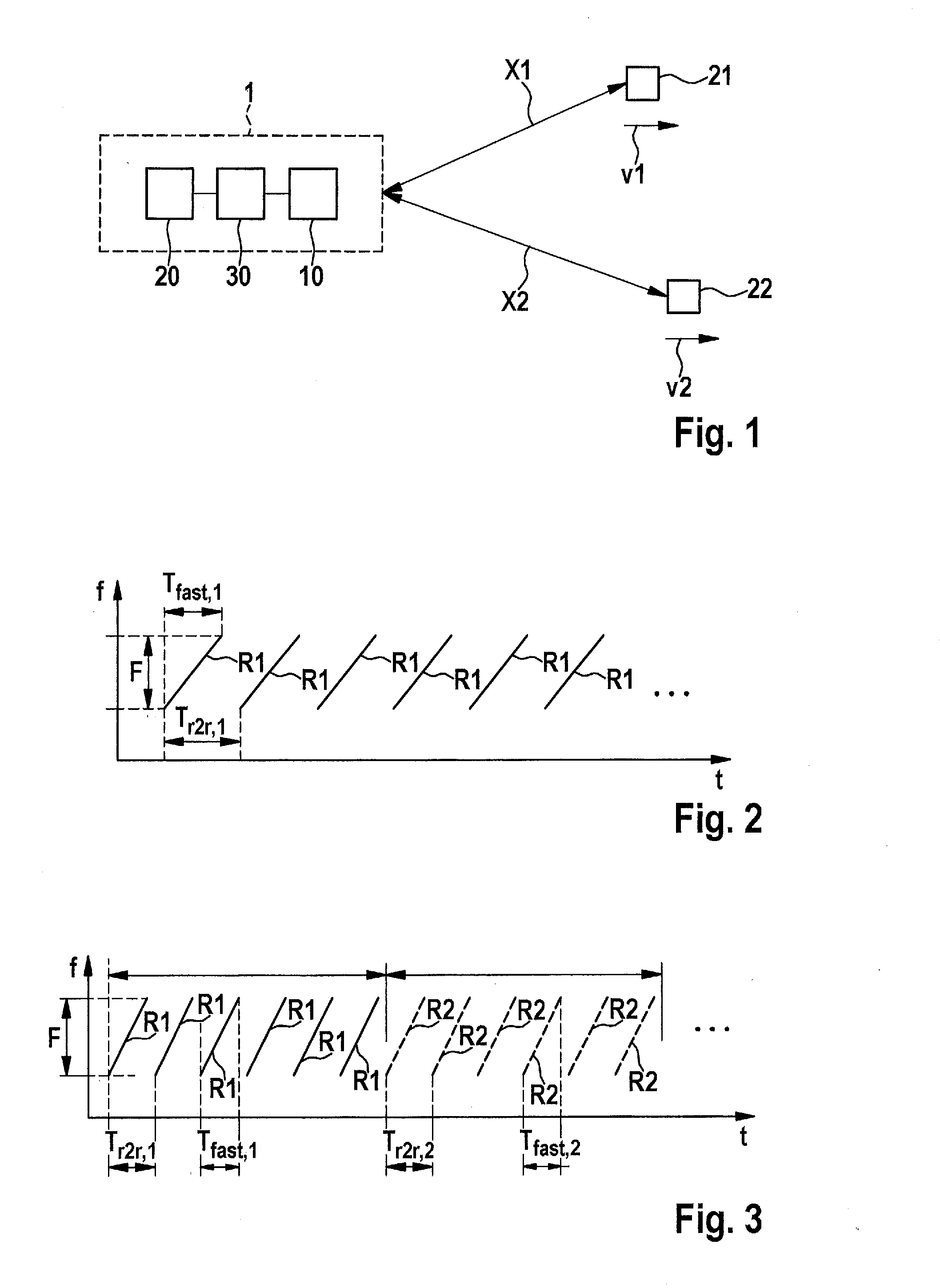
[0031]FIG. 1 shows a radar system 1 according to one exemplary embodiment of the present invention. For example, radar sensor 1 may be a radar sensor of a driver assistance system. Such driver assistance systems are preferably used in modern motor vehicles.

[0032]Radar system 1 includes a transceiver unit 10. This transceiver unit 10 transmits a sequence of modulated rapid-chirp radar signals. These transmitted rapid-chirp radar signals strike objects 21 and 22 which are situated at respective distances X1 and X2 from radar sensor 1. Objects 21 and 22 move relative to radar sensor 1 at velocities v1 and v2. In addition, it is also possible that the additional objects are situated in the detection range of radar sensor 1. Distances X1 and X2 and relative velocities v1 and v2 of the individual objects may be different. However, it is also possible that distances X1 and X2 and relative velocities v1 and v2 of some objects are completely or approximately equal.

[0033]The modulated rapid-c...


PUM


Abstract

In a method for operating a radar sensor, the unambiguousness range of the radar sensor is increased with respect to the range and / or the relative velocity by: transmitting multiple ramp sets by the radar sensor, the frequency ramps of the individual ramp sets each differing in one system parameter; adapting the sampling frequency during the detection of the radar echoes in such a way that a constant number of samples always results for each frequency ramp; and, to evaluate the radar signals, the spectra are periodically continued and compared to each other.

Description

BACKGROUND OF THE INVENTION[0001]1. Field of the Invention[0002]The present invention relates to a radar sensor and a method for operating a radar sensor, e.g., a radar sensor having rapid-chirp radar signals.[0003]2. Description of the Related Art[0004]Modern motor vehicles increasingly have driver assistance systems for supporting a vehicle driver when driving the motor vehicle. For example, such driver assistance systems may inform the vehicle driver about an obstacle while parking. In addition, driver assistance systems may also support the vehicle driver during travel by, for example, detecting an obstacle on the travel route of the motor vehicle and then signaling this potential hazard to the vehicle driver, or possibly even actively intervening into the driving behavior of the motor vehicle.[0005]LFMCW (linear frequency modulated continuous wave) modulation of the radar signals has been used very frequently in the automotive field up to now, due to the low hardware complexity...

Claims


Application Information

Patent Timeline
IPC IPC(8): G01S7/35G01S13/02G01S13/931
CPCG01S13/02G01S7/35G01S13/931G01S13/345G01S13/34G01S13/343G01S13/584
Inventor BI, JINGYINGKUEHNLE, GOETZ
Owner ROBERT BOSCH GMBH
Why Eureka
Try Eureka