Method and system for testing internal condensation condition of battery

A test method and water-cooling system technology, applied in the direction of measuring electricity, measuring devices, measuring electrical variables, etc., can solve the problems of reducing electrical clearance and creepage distance, large measurement error, high-voltage leakage, etc., and achieve strong replaceability and test low cost effect

Active Publication Date: 2020-11-27
东风时代(武汉)电池系统有限公司
View PDF6 Cites 1 Cited by
  • Summary
  • Abstract
  • Description
  • Claims
  • Application Information

AI Technical Summary

Problems solved by technology

[0002] Batteries are the core components of power vehicles. At present, power battery systems are generally equipped with explosion-proof valves containing waterproof and breathable membranes in order to prevent internal thermal runaway battery exhaust and internal and external air pressure balance. The waterproof and breathable membranes allow water vapor to pass through; power batteries The system also generally uses a water-cooling system connected to the vehicle. When an electric vehicle is driving or charging in a high-temperature and high-humidity environment, the water-cooling system will feed low-temperature coolant, and the water vapor in the battery system will form condensed water on the water-cooling plate. External water vapor penetrates into the battery system and causes continuous condensation; when the electric vehicle is continuously used in a high-temperature and high-humidity environment, the internal condensation accumulates and the humidity increases, and the modules, copper bars, and power distribution boxes inside the battery system are damaged. Water mist may appear, greatly reducing electrical clearance and creepage distance, endangering high-voltage safety
[0003] In related technologies, it is possible to directly use the battery pack to perform charging and discharging in an external hot and humid environment and then weigh it. Risks such as high pressure leakage are likely to occur, threatening the safety of test equipment and personnel

Method used


Image

  • Method and system for testing internal condensation condition of battery
  • Method and system for testing internal condensation condition of battery

Examples


Embodiment Construction

[0020] In order to make the purpose, technical solutions and advantages of the embodiments of the present invention clearer, the technical solutions in the embodiments of the present invention will be clearly and completely described below in conjunction with the drawings in the embodiments of the present invention. Obviously, the described embodiments It is a part of embodiments of the present invention, but not all embodiments. Based on the embodiments of the present invention, all other embodiments obtained by persons of ordinary skill in the art without making creative efforts belong to the protection scope of the present invention.

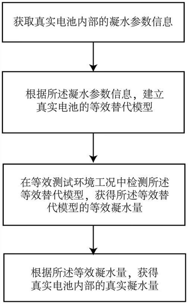
[0021] see figure 1 As shown; the embodiment of the present invention provides a test method for the internal condensation condition of the battery, including the following steps: obtaining the condensation parameter information inside the real battery; according to the condensation parameter information, establishing an equivalent replacemen...


PUM


Abstract

The invention relates to a method and system for testing the internal condensation condition of a battery. The method for testing the internal condensation condition of the battery comprises the following steps: acquiring real internal condensation parameter information of the battery; establishing an equivalent substitution model of a real battery according to the water condensation parameter information; detecting the equivalent substitution model in the equivalent test environment working condition, and acquiring the equivalent condensate amount of the equivalent substitution model; according to the equivalent condensed water amount, obtaining a real condensed water amount in a real battery. Therefore, by establishing the equivalent substitution model, the real condensate amount in thereal battery can be obtained; meanwhile, the equivalent substitution model can be disassembled, assembled and replaced at any time, the test cost is lower than the test cost of the real battery, and through the equivalent substitution model, the safety of experimental equipment personnel is prevented from being harmed due to high-voltage leakage of the real battery.

Description

technical field [0001] The invention relates to the technical field of battery condensation testing, in particular to a method and system for testing the internal condensation of batteries. Background technique [0002] Batteries are the core components of power vehicles. At present, power battery systems are generally equipped with explosion-proof valves containing waterproof and breathable membranes in order to prevent internal thermal runaway battery exhaust and internal and external air pressure balance. The waterproof and breathable membranes allow water vapor to pass through; power batteries The system also generally uses a water-cooling system connected to the vehicle. When an electric vehicle is driving or charging in a high-temperature and high-humidity environment, the water-cooling system will feed low-temperature coolant, and the water vapor in the battery system will form condensed water on the water-cooling plate. External water vapor penetrates into the batter...

Claims


Application Information

Patent Timeline
Patent Type & Authority Applications(China)
IPC IPC(8): G01R31/367G01R31/385
CPCG01R31/367G01R31/385Y02E60/10
Inventor 钱爽
Owner 东风时代(武汉)电池系统有限公司
Why Eureka
Try Eureka