Heat pipe type roller vacuum dryer

A drum vacuum and heat pipe type technology, applied in dryers, non-progressive dryers, drying, etc., can solve the problem of limited heating area of ​​heat-conducting working medium, insufficient total heat energy of heat-conducting working medium, and lack of heat energy for materials, etc. question

Inactive Publication Date: 2020-11-27
MENGZHOU YUANHONG DRYING EQUIP RES & DEV CO LTD
View PDF1 Cites 0 Cited by
  • Summary
  • Abstract
  • Description
  • Claims
  • Application Information

AI Technical Summary

Problems solved by technology

The heat conduction area of ​​the heating plate at the lower end of the heating tube is limited, and the heating plate with a small heat exchange area only inputs a small amount of heat. The heat conduction working fluid affects the heat energy in the heat conduction tube to the inner cavity of the tube due to the limited heating area. The heat conduction heating of the heat-conducting working medium causes the total heat energy of the heat-conducting working medium to be insufficient, causing the heating tube to fail to output a large amount of heat energy, and the material cannot receive enough heat energy, which affects the drying efficiency of the drum drying chamber

Method used


Image

  • Heat pipe type roller vacuum dryer
  • Heat pipe type roller vacuum dryer
  • Heat pipe type roller vacuum dryer

Examples


Embodiment

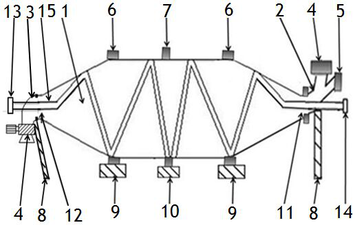
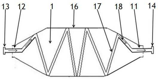
[0096] Such as figure 1 The shown heat pipe drum vacuum dryer includes a drum drying chamber 1, a raceway 6, a gear ring 7, a tee joint device 2, an elbow joint device 3, a discharge device 4, a vacuum unit 5, a bracket 8, and supporting wheels 9. Drive device 10.

[0097] The drum drying bin 1 has an inlet port 11 and an outlet port 12 .

[0098] The outer diameter of the drum drying bin 1 is 1800 mm; the length of the drum drying bin 1 is 8000 mm.

[0099] The gear ring 7 and the raceway 6 are connected and fixed together with the cylinder body 29 of the drum drying bin 1; the supporting roller 9 supports the raceway 6 of the drum drying bin 1 .

[0100] The drive device 10 is a hydraulic motor.

[0101] The drum drying bin 1 is driven by the driving device 10 , and the drum drying bin 1 rotates on the supporting wheel 9 .

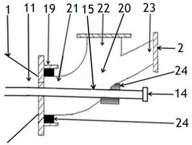
[0102] Such as figure 1 , figure 2 , image 3 The three-way joint device 2 shown includes a three-way pipe 20 , a flange joint 19 and a dynamic ...


PUM


Abstract

The invention discloses a heat pipe type roller vacuum dryer. The heat pipe type roller vacuum dryer comprises a roller drying bin, roller paths, a gear ring, a three-way joint device, an elbow connector device, discharging devices, a vacuum unit, brackets, riding wheels and a driving device, wherein a heating device comprises heating pipes, a heat conduction pipe and fixing strips; the heating pipes comprise metal pipes, heat conduction working media and heating end sockets; the heating end sockets comprise heating plates, heat conduction working media and heaters; heat energy carried by themedia in the heat conduction pipes of the heating devices carries out heat conduction heating on the heating end sockets through pipe bodies of the heat conduction pipes; the heat dissipation areas ofheaters with heating strips of the heating end sockets are increased by 8-35 times; liquid heat conduction working media in the pipe inner cavities of the heating pipes are vaporized after being subjected to heat conduction heating by heat energy on the heaters of the heating end sockets; the heat conduction working media perform liquid-vapor phase change heat conduction heat exchange in the pipeinner cavities; and heat energy carried by the heat conduction working media is conducted to materials outside the metal pipes through the metal pipes for performing heat conduction heating, so thatthe heat conduction drying effect on the materials is improved.

Description

technical field [0001] The invention relates to a drum dryer, in particular to a heat pipe type drum vacuum dryer. Background technique [0002] Nowadays, in the processing and production fields of grain, food, chemical industry, medicine, agricultural by-products, pasture, etc., it is necessary to heat and dry the materials; the hot air used in the drum dryer is the hot air exchanged through the heat exchanger outside the equipment, or the drum A heating chamber needs to be installed outside the drying chamber. The heating tank conducts heat to the cylinder of the drum drying chamber. The heat energy can only be used through secondary heat exchange. The heat exchange efficiency of heat energy is low. The use of heat energy is one-time, and the heat energy can be used effectively. If the efficiency is low, the heat energy required for drying will increase a lot. [0003] In some drum dryers, the heat energy used when drying the material in the drum drying bin is heated by t...

Claims


Application Information

Patent Timeline
Patent Type & Authority Applications(China)
IPC IPC(8): F26B11/06F26B23/10F26B25/00F26B25/16F26B5/04
CPCF26B5/04F26B11/0486F26B23/10F26B25/002F26B25/16
Inventor 程长青代爱妮
Owner MENGZHOU YUANHONG DRYING EQUIP RES & DEV CO LTD
Why Eureka
Try Eureka