
In-place non-contact detection method for shaft type workpiece

A technology for shaft workpieces and detection methods, which is applied to metal processing machinery parts, manufacturing tools, metal processing equipment, etc., can solve the problem that the machining accuracy of camshaft journal runout is very high, and cannot adapt to high-precision and high-efficiency large-scale production models. Problems such as low measurement efficiency

Active Publication Date: 2020-11-27
JIANGSU UNIV OF SCI & TECH
View PDF7 Cites 16 Cited by
  • Summary
  • Abstract
  • Description
  • Claims
  • Application Information

AI Technical Summary

Problems solved by technology

Among them, the machining accuracy of camshaft journal runout is very high, and it is also a must-check item for inspection. Traditional optical mechanical measuring instruments, contact probe measuring instruments and sample measurement efficiency are extremely low and most of them need to be carried out offline, which cannot adapt to today's high-precision and efficient scale. The needs of the production mode

Method used


Image

  • In-place non-contact detection method for shaft type workpiece
  • In-place non-contact detection method for shaft type workpiece
  • In-place non-contact detection method for shaft type workpiece

Examples


Embodiment

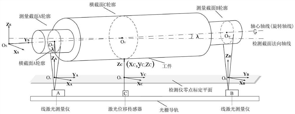
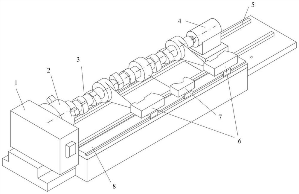
[0256] Taking the camshaft produced by a diesel engine factory as an example, the diameter of the camshaft journal is 180mm, the length is 1780mm, the runout tolerance requirement is 0.05mm, the coaxiality tolerance requirement is 0.05mm, and the camshaft profile requirement is 0.08mm. Therefore, according to the size of the camshaft to be detected, the line laser measuring instrument of the detection device selects a certain LJ-X8400 type, which can measure a maximum width of 320mm and has a precision of 5um; the CCD laser displacement sensor selects a certain LK-G400 type, with a precision of 2um and a measurable range of 400±100mm .

[0257] Place the detection system on one side of the machine tool, place the camshaft in the workpiece clamping device calibrated with the detection system above, align the optical path of the line laser measuring instrument with the reference axis section of the workpiece, and start the line laser measurement of positions A and B measuring in...


PUM


Abstract

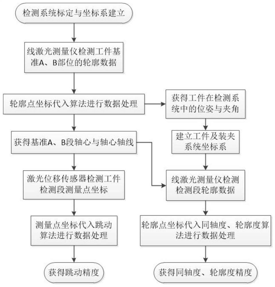
The invention discloses an in-place non-contact detection method for a shaft type workpiece. The in-place non-contact detection method for the shaft type workpiece comprises the following steps that adetection system is established, the detection system is demarcated, and the detection coordinate system is established; the pose of the workpiece in the detection system is analyzed, and the coordinate system of a workpiece clamping device is established; a clamping device of a shaft type workpiece machining machine tool is controlled to rotate, continuous data collection is conducted by a linelaser measurement instrument, computational analysis is conducted on collected data, and the ideal datum axis of the axle type workpiece is acquired; continuous data collection is conduct on a detected position by a laser displacement sensor, computational analysis is conducted on collected data, and the actual jumping machining accuracy of the shaft neck of a cam shaft is acquired; and the line laser measurement instrument is adopted to conduct continuous data collection on the detected position, computational analysis is conducted on collected data, and the coaxiality machining accuracy of the shaft type workpiece is acquired. By means of the in-place non-contact detection method for the shaft type workpiece, the shaft neck circle center and the ideal datum axis thereof of the shaft typeworkpiece can be detected in real time, and systematic errors and compensatory difficulties brought about by traditional use of ejector pin standards or a V-shape block are avoided.

Description

technical field [0001] The invention relates to a detection method for shaft workpieces in the processing field, in particular to a non-contact detection method for shaft workpieces in-position. Background technique [0002] The camshaft is a part of the piston engine. Its function is to control the opening and closing of the valve. The main body of the camshaft is a cylindrical rod with approximately the same length as the cylinder group. There are several journals on it and several bushes between the journals. A cam is used to drive the valve. The camshaft is the core component of the engine, and its machining accuracy directly affects the overall performance indicators of the engine such as noise, power performance, and economy. Among them, the machining accuracy of camshaft journal runout is very high, and it is also a must-check item for inspection. Traditional optical mechanical measuring instruments, contact probe measuring instruments and sample measurement efficien...

Claims


Application Information

Patent Timeline
IPC IPC(8): B23Q17/20
CPCB23Q17/20G05B19/401G05B2219/37194G05B2219/37573G05B2219/37582G01B11/03G01B11/026
Inventor 李国超刘云龙周宏根冯丰赵东豪周浩于丹平韩冬梅朱建伟
Owner JIANGSU UNIV OF SCI & TECH
Learn More