
Integrated machining equipment for automatically positioning and bending three-groove bent iron plate

An automatic positioning and processing equipment technology, applied in the field of iron plate bending, can solve the problems of many manual operation parts, time-consuming and labor-intensive processing, scattered steps, etc., and achieve the effect of avoiding manual transfer

Inactive Publication Date: 2020-11-27
东莞市夯牛机电科技有限公司
View PDF0 Cites 0 Cited by
  • Summary
  • Abstract
  • Description
  • Claims
  • Application Information

AI Technical Summary

Problems solved by technology

[0004] Aiming at the deficiencies of the existing technology, the present invention provides an integrated processing equipment for automatic positioning and bending of three-groove bent iron plates, which solves the problem of cutting and growing the iron plates during the processing of three-groove bent iron plates proposed in the background technology. Strip shape, and then the long iron plate is manually placed in the fixture, and the two sides are symmetrically drilled, and then the drilled iron plate is placed in the bending machine to be processed into a U shape, while the iron plate in the three grooves The steps in the processing of the board are scattered, and there are many manual operations, so the processing is time-consuming and labor-intensive.

Method used

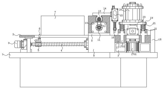
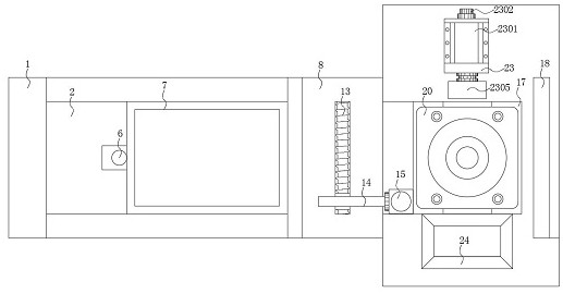
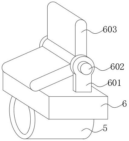

Image

  • Integrated machining equipment for automatically positioning and bending three-groove bent iron plate
  • Integrated machining equipment for automatically positioning and bending three-groove bent iron plate
  • Integrated machining equipment for automatically positioning and bending three-groove bent iron plate

Examples


Embodiment Construction

[0027] The following will clearly and completely describe the technical solutions in the embodiments of the present invention with reference to the accompanying drawings in the embodiments of the present invention. Obviously, the described embodiments are only some, not all, embodiments of the present invention.

[0028] In the description of the present invention, unless otherwise stated, the meaning of "plurality" is two or more; the terms "upper", "lower", "left", "right", "inner", "outer" , "front end", "rear end", "head", "tail", etc. indicate the orientation or positional relationship based on the orientation or positional relationship shown in the drawings, and are only for the convenience of describing the present invention and simplifying the description, rather than indicates or implies that the device or element referred to must have a particular orientation, be constructed and operate in a particular orientation, and therefore should not be construed as limiting the...


PUM


Abstract

The invention discloses integrated machining equipment for automatically positioning and bending a three-groove bent iron plate. The integrated machining equipment comprises a bottom machine box, a support is installed on the left side of the upper surface of the bottom machine box, and a feeding bin is arranged on the right side of the upper surface of the support; a flow guide clamping groove isformed in the center line of a fixing base, an operation table is installed on the right side of the fixing base, and a supporting base is arranged above the operation table; and a pushing mechanismis arranged on the surface of the right side of the bottom machine box, and a discharging port is formed in the surface of the right side of the bottom machine box. According to the integrated machining equipment, a feeding mechanism, a laser cutting machine box and the operation table are arranged above the bottom machine box, through one-time arrangement of the feeding mechanism, the laser cutting machine box and the operation table, a set of assembly line is conveniently formed, and a punching hydraulic cylinder is arranged above the operation table, so that punching and bending are conveniently combined into a whole, manual feeding and discharging of an operator and manual transferring of iron plate machining are avoided, and thus the working efficiency of machining an iron plate intothe three-groove bent iron plate is favorably improved.

Description

technical field [0001] The invention relates to the technical field of iron plate bending, in particular to an integrated processing equipment for automatic positioning and bending of three-groove bent iron plates. Background technique [0002] The three-groove bending iron plate is to bend the iron plate into a U shape and wrap the workpiece inside. It is a fastener and is also called a hoop. It is formed by joining the left and right halves of the hoop. Both the left and right halves of the hoop are in the shape of a semi-circle, and the two ends of the semi-circle are bent outwards to form a mounting ear. The mounting ear at one end of the left half of the hoop is provided with a slot. There is a pin on the mounting ear at the corresponding end of the matching right half of the hoop, and the pin on the mounting ear at one end of the right half of the hoop is inserted into the slot on the mounting ear at one end of the left half of the hoop. There are many kinds of hoops, ...

Claims


Application Information

Patent Timeline
IPC IPC(8): B23P23/04
CPCB23P23/04
Inventor 张绍辉胡展铭陈咏诗
Owner 东莞市夯牛机电科技有限公司
Learn More