
Denitration system

A denitrification and flue technology, applied in the field of denitrification system, can solve the problems of low temperature of reductant flue gas, blockage of catalyst layer, deviation of denitrification efficiency, etc., to solve the problem of low flue gas temperature, avoid inlet deflection angle, and strengthen gas disturbance Effect

Pending Publication Date: 2020-11-27
XI AN JIAOTONG UNIV
View PDF0 Cites 1 Cited by
  • Summary
  • Abstract
  • Description
  • Claims
  • Application Information

AI Technical Summary

Problems solved by technology

[0009] The purpose of the present invention is to overcome the above-mentioned shortcomings of the prior art, and to provide a denitrification system, which can effectively solve the problems in the prior art where the denitrification efficiency deviates from the design value, the mixing of ammonia gas and flue gas is insufficient, and the injection amount of ammonia gas is different from that of the design value. The proportion of flue gas cannot be controlled, the catalyst layer is prone to blockage, and the flue gas temperature of the reducing agent entering the SCR flue is low

Method used


Image

  • Denitration system
  • Denitration system

Examples


Embodiment Construction

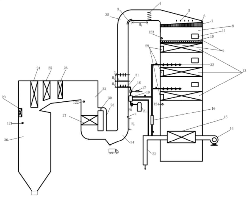
[0027] The present invention is described in further detail below in conjunction with accompanying drawing:

[0028] refer to figure 1 and figure 2 The denitrification system described in the present invention includes a furnace 36, a boiler tail flue 33, a first turning flue 34, a first vertical flue, a second turning flue 35, a horizontal flue, an SCR flue expansion section, a second Two vertical flues, signal device 17, ammonia injection controller 18, buffer tank 19, urea / liquid ammonia storage tank 21 and air supply pipe 22; furnace 36, boiler tail flue 33, first diverting flue 34, second flue A vertical flue, a second turning flue 35, a horizontal flue, an expansion section of the SCR flue, and a second vertical flue are arranged in sequence along the direction of flue gas flow, wherein the first vertical flue is provided with an ammonia spray grid A grid 31, a first probe 121 and an SNCR ammonia injection device 23 are arranged in the furnace 36, and a panel superhea...


PUM


Abstract

The invention discloses a denitration system. According to the denitration system, a first probe and an SNCR ammonia spraying device are arranged in a hearth, and a platen superheater, a high-temperature superheater, a low-temperature superheater and a second probe are sequentially arranged in a tail flue of a boiler in a flue gas flowing direction; a reactor and an air preheater are arranged in asecond vertical flue in the flue gas flowing direction, a third probe, a catalyst layer and a fourth probe are sequentially arranged in the reactor in the flue gas flowing direction, and the output end of an annunciator is connected with the input end of an ammonia spraying controller; the outlet of the ammonia spraying controller communicates with the inlet of an ammonia spraying grid; the inletof the ammonia spraying controller communicates with the heat absorption side outlet of a buffer tank; and the heat absorption side inlet of the buffer tank communicates with the outlet of a urea / liquid ammonia storage tank through a solution pump. The system can effectively solve the problems that denitration efficiency deviates from a design value, ammonia gas and flue gas are insufficiently mixed, the injection amount of the ammonia gas and the proportion of the flue gas cannot be controlled, a catalyst layer is prone to blockage, and the temperature of the flue gas, entering an SCR flue,of a reducing agent is low in the prior art.

Description

technical field [0001] The invention belongs to the technical field of boilers and relates to a denitrification system. Background technique [0002] With the rapid development of the economy, the problem of environmental pollution is becoming more and more serious. The soot, sulfur dioxide and nitrogen oxides contained in the fuel flue gas are the main sources of air pollution, acid rain and greenhouse effect. Among many denitrification technologies, Selective Catalytic Reduction (SCR) is a relatively mature denitrification technology at home and abroad. It has high denitrification efficiency but high cost. Low. [0003] The current denitrification device has the following disadvantages: [0004] 1. When the boiler is operating at low load, the flue gas temperature deviates from the optimum reaction temperature of the catalyst, resulting in insufficient reaction between ammonia and flue gas, and the denitrification efficiency deviates from the design value. [0005] 2. T...

Claims


Application Information

Patent Timeline
Patent Type & Authority Applications(China)
IPC IPC(8): B01D53/86B01D53/78B01D53/56
CPCB01D53/56B01D53/78B01D53/8625B01D2251/2062B01D2258/0283
Inventor 邓磊铁渊白冰张妍吴宇浩车得福
Owner XI AN JIAOTONG UNIV
Learn More