
Multipath water treatment control valve

A technology for water treatment and valve control, applied in multi-port valves, valve devices, mechanical equipment, etc., can solve the problems of affecting the output of through-hole water flow, reducing water flow output, and small water flow, so as to reduce production costs and reduce production costs. The effect of improving water quality and increasing water flow

Inactive Publication Date: 2008-12-24
陈锋
View PDF6 Cites 0 Cited by
  • Summary
  • Abstract
  • Description
  • Claims
  • Application Information

AI Technical Summary

Problems solved by technology

Like this just needs to be provided with a plurality of flowing water through-holes on the sealing end face of described fixed valve plate, its existence is insufficient: the one, because each through-hole is limited by its structural size, the cross-sectional area of ​​through-hole is less, seriously affects The output of the water flow in the through hole
The end face of the movable valve plate is provided with a radial blind hole from the central hole to the edge, because the blind hole should correspond to the communication position of the plurality of through holes provided on the fixed valve plate, so the diameter is limited. The indexing angle to the opening of the blind hole should not be too large, resulting in a reduction in the flow cross-sectional area of ​​the blind hole, directly resulting in a reduction in the output of water flow
Seriously affected people's demand for large-flow water in production or life
The second is that when the blind hole provided on the end face of the movable valve plate is switched to the working position, the blind hole is easily communicated with two adjacent through holes of which there are multiple through holes on the fixed valve plate. The raw water enters the water purification channel and is directly discharged outward, which seriously affects the quality of water treatment
The third is that during the backwashing work, due to the limitation of the small cross-sectional area of ​​the through hole of the fixed valve plate, the backwashing water flow through the through hole is obviously less than the normal working water flow. Small, incomplete flushing will cause blockage, hardening or failure of the filter material, directly resulting in a decline in the quality of the water treated
[0003] In addition, the water treatment control valves in the prior art can only be installed with single-purpose filter valves, downstream regeneration softening valves or countercurrent regeneration valves when people filter, downstream regeneration and softening or countercurrent regeneration softening treatment respectively. The softening valve can only be realized, and the special valve will obviously increase the production cost of the water treatment control valve

Method used


Image

  • Multipath water treatment control valve
  • Multipath water treatment control valve
  • Multipath water treatment control valve

Examples


Embodiment 1

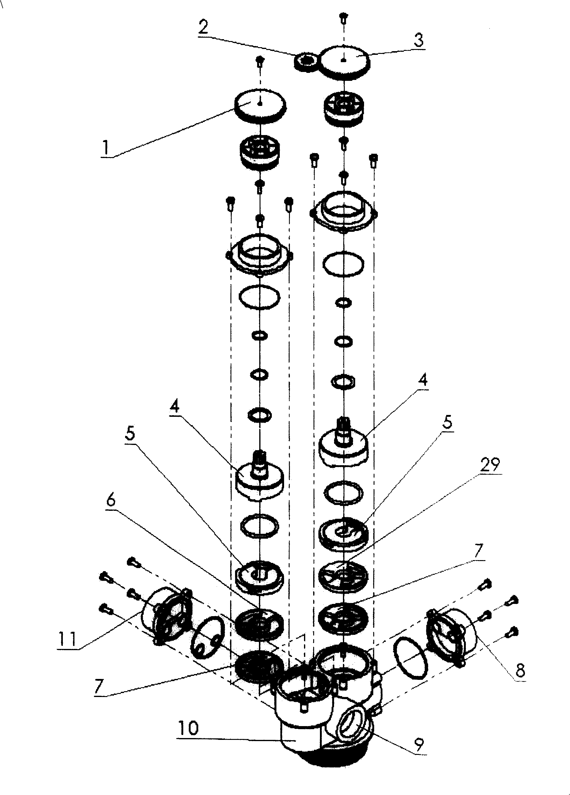
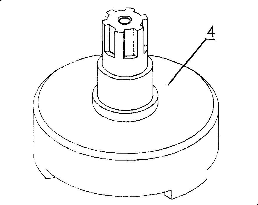
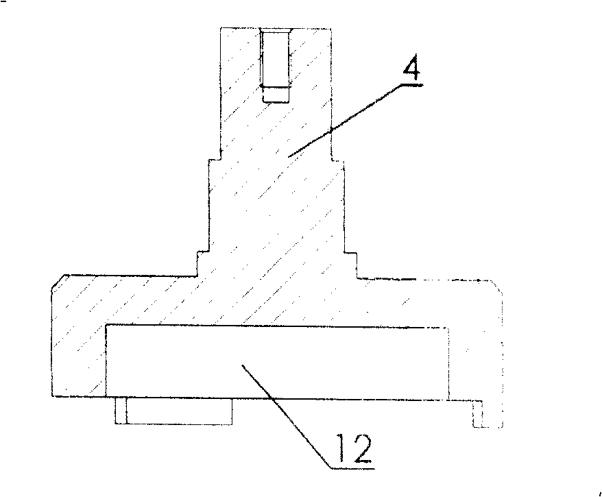
[0060] Embodiment one, Figure 1 to Figure 14 shown. This multi-channel water treatment control valve mainly includes a valve body connected with raw water inlet, clean water outlet and sewage outlet, and a valve core connected to the valve stem is placed in the valve body; the valve core connected to the valve stem 4 , placed in the left and right valve chambers of the valve body 10; the valve core is composed of a movable valve plate 5 and a fixed valve plate 6, 29 with left and right two pairs of end faces sealed and matched with each other; the two movable valves The end face of the sheet 5 and the end face of the valve stem 4 are respectively fitted and connected by grooves and protrusions ( Figure 2-Figure 5 shown); in order to increase the water flow and circulation space, a volume groove 12 is provided on the fitting end surface of the valve rod 4; on the end surface of the movable valve plate 5, a radially extending To the scalloped through hole 13 of its edge ( ...

Embodiment 2

[0061] Embodiment two, Figure 15-Figure 16 shown. The structure of the present invention is the same as that of the first embodiment and will not be described in detail. Its difference is, described valve body raw water inlet 11 place is connected with salt valve 25; The two salt input holes 30 of described salt valve 25 communicate with the salt inlet 31 and 32 on the valve body respectively ( Figure 13 ~ Figure 14 shown). On the end face between the water inlet hole 14 and the drain hole 16, the left fixed valve plate 6 is provided with a fan-shaped salt hole 23, which can be used as a downstream regeneration softening valve for water treatment.

Embodiment 3

[0062] Embodiment three, Figure 17-Figure 18 shown. The structure of the present invention is the same as that of the first embodiment and will not be described in detail. Its difference is that the raw water inlet 11 of the valve body is connected with a salt valve 25; the two salt input holes 30 of the salt valve 25 communicate with the salt inlets 31 and 32 on the valve body respectively ( Figure 13-Figure 14 shown). On the end face of the right fixed valve plate 29 provided with the water inlet hole 14 and the drain hole 16, a fan-shaped salt hole 23 is added. It can also be used as a countercurrent regeneration softening valve for water treatment.


PUM


Abstract

A multiple water treatment control valve mainly includes moving and fixed valve blocks disposed in the valve body, a valve-stem scarf jointed with the moving valve block, a volume slot disposed on the mosaic end surface of the valve-stem, a fan through-hole radial extended from the central hole to its edge, upper and lower water spreading nozzles on left and right fixed valve blocks in communication with upper and lower water spreaders connecting holes through upper and lower water spreading nozzles of the valve body, a fan water inlet, a water outlet, a blowoff hole and a salt hole on left and right fixed valve blocks are separately connected with a raw water inlet, a clean water outlet, a blowoff hole and salt-feeding hole on the valve body through the runner and a fixed connecting plate at the bottom of the left and right fixed valve blocks connected with the valve body to be sealed.

Description

(1) Technical field: [0001] The invention relates to a waterway control device; in particular, it relates to a multi-channel water treatment control valve. (two) background technology: [0002] In the prior art, for small flow water treatment control valves used in production or daily life (the water flow rate is generally ≤6T / h), the valve core is usually a movable valve plate and a fixed valve with a pair of end faces that are sealed and connected to each other. By rotating the movable valve plate, the output of the water flow in the valve core is controlled and the direction, time and flow rate of the water flow output are changed, so as to carry out backwashing, positive flushing and normal operation of the filter material (such as activated carbon, quartz sand) respectively. , realize the purification treatment of water; or carry out backwashing, salt absorption, positive flushing, water injection and normal work on the filter material (such as ion exchange resin), so a...

Claims


Application Information

Patent Timeline
IPC IPC(8): F16K11/22
Inventor 王承丰孟凡刚李春宇于恒波
Owner 陈锋
Learn More