
Sewerage system and method for bottom of box tank

A bottom sewage and tank technology, which is applied in the field of tank bottom sewage system, can solve the problems of sewage outlet blockage, poor discharge cleanliness, fouling, etc., to reduce the probability of pipeline blockage, improve the import form, and ensure normal operation running effect

Pending Publication Date: 2018-11-02
DATANG ENVIRONMENT IND GRP
View PDF9 Cites 0 Cited by
  • Summary
  • Abstract
  • Description
  • Claims
  • Application Information

AI Technical Summary

Problems solved by technology

[0003] In order to solve the above-mentioned technical problems, the present invention provides a sewage discharge system and method at the bottom of the tank body. Its purpose is to provide a sewage discharge system and a sewage discharge method at the bottom of the tank body. Small, the sewage outlet is prone to blockage and scaling, the sewage discharge method is too simple, and the cleanliness is poor

Method used


Image

  • Sewerage system and method for bottom of box tank
  • Sewerage system and method for bottom of box tank

Examples


Embodiment 1

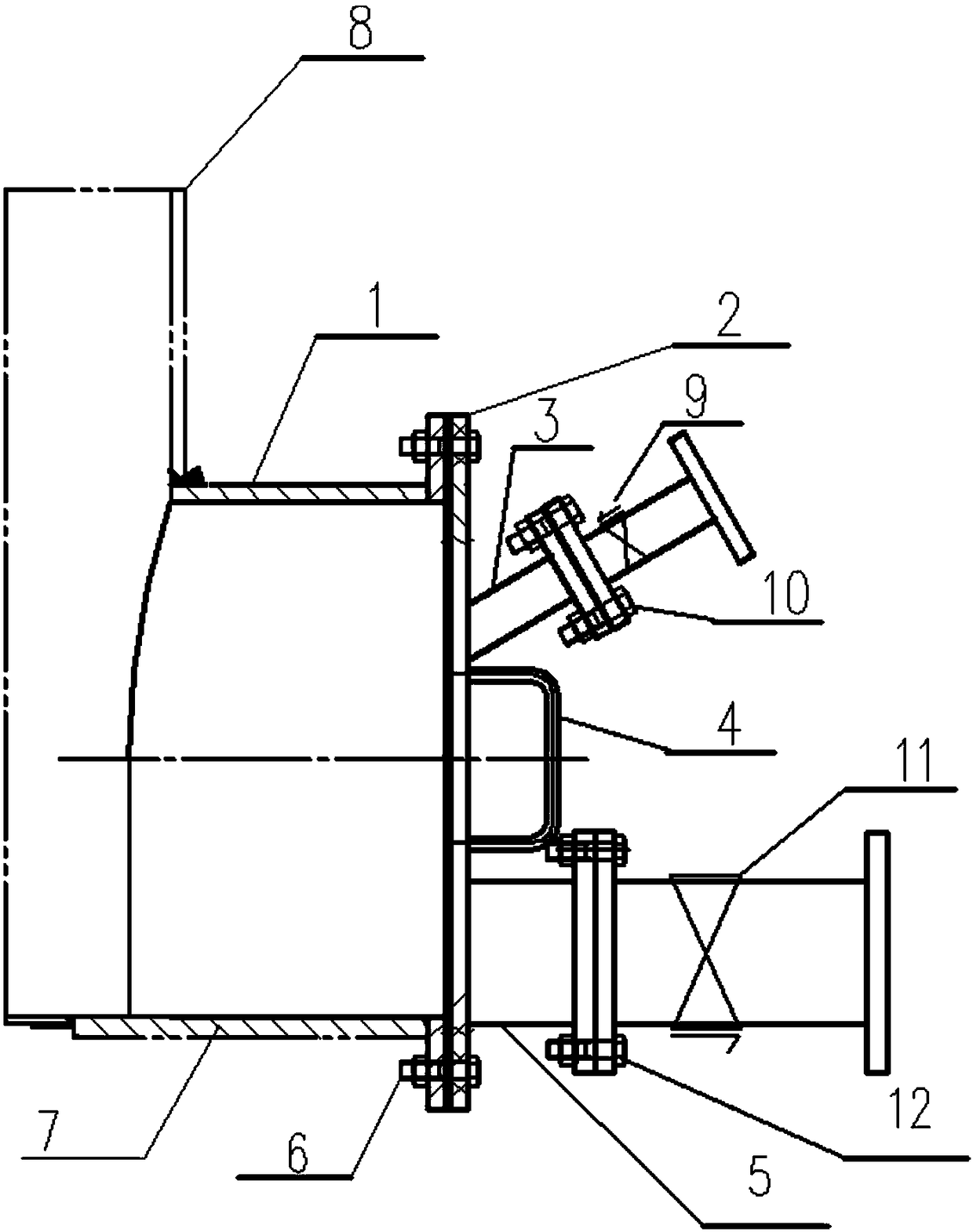
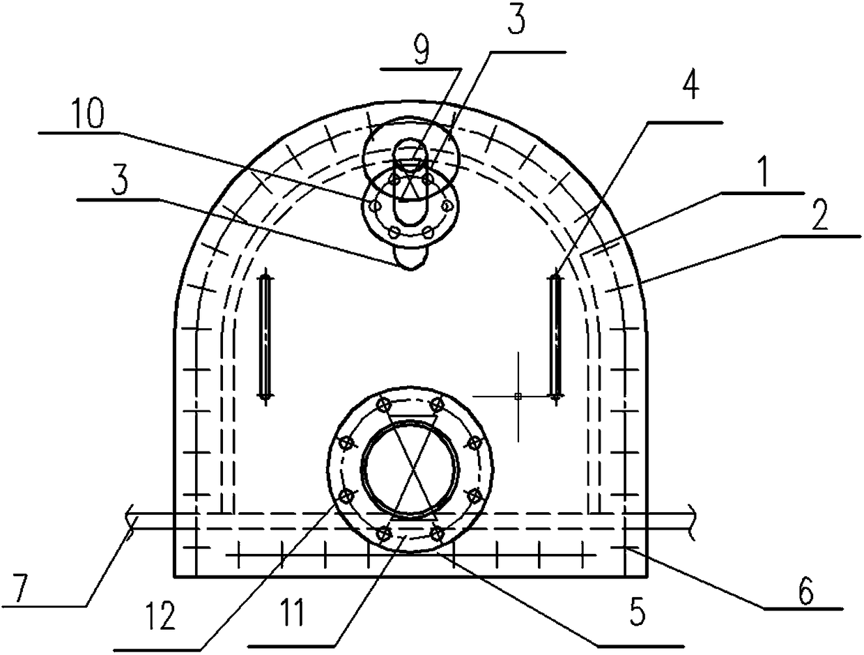
[0029] Example 1, such as figure 1 , 2 As shown, the sewage system at the bottom of the tank body described in the first embodiment of the present invention includes:

[0030] The cleaning device comprises a cleaning port 1, a flange cover 2 of the cleaning port, and a basic ring 7. One end of the cleaning port 1 is installed on the bottom side of the tank body 8, and the other end of the cleaning port 1 is connected to the The flange cover 2 of the clean discharge port is described, the flange cover 2 of the clean discharge port is provided with at least one oval opening and a circular opening, and the basic ring 7 is placed at the bottom of the clean discharge port 1;

[0031] At least two handles 4;

[0032] The connection between the handle 4 and the flange cover 2 of the drain port is welding;

[0033] The connection between the drain port 1 and the tank body 8 is welding;

[0034] The drain port 1 and the drain port flange cover 2 are fixedly connected by bolts C6; ...

Embodiment 2

[0042] Embodiment 2, the bottom sewage discharge method of the tank body of the second embodiment of the present invention includes:

[0043] Step 1, open all the one-way valves A9, and the flushing liquid enters the drain port 1 through the flushing pipes 3 from the outside, and flushes the dirty liquid in the drain port 1 for 1 minute;

[0044] Step 2, close all the one-way valves A9, open the one-way valve B11, and the dirty liquid in the tank body 8 is discharged through the discharge port 1 and the sewage pipe 5 in sequence;

[0045] Step 3, when no dirty liquid flows out, open all the one-way valves A9 again to flush the dirty liquid in the drain port 1 for 1 minute;

[0046] Step 4, close all one-way valves A9;

[0047] Step 5, when no dirty liquid flows out, close the one-way valve B11.

[0048] The pressure of the flushing liquid in the flushing pipeline 3 is 0.3 MPa.

[0049] This embodiment has the following beneficial effects: use high-pressure flushing liquid t...


PUM


Abstract

The invention relates to a sewerage system and method for the bottom of a box tank. The sewerage system for the bottom of the box tank comprises an emptying device, at least one flushing device and asewerage device; the emptying device comprises an emptying opening, a emptying opening flange cover, and a base ring; each flushing device comprises a flushing pipeline and a one-way valve A; the sewerage device comprises a sewerage pipeline, and a one-way valve B; and through the addition of the emptying device, the inlet form of the sewerage system is improved so as to solve the problem that blockage and scaling are easily take place due to the too small sewerage opening, and the probability of pipeline blockage in the front of the sewerage opening is reduced; and meanwhile, through the addition of the flushing devices of the sewerage opening, the sewerage inlet can be effectively flushed before and after the operation of the sewerage opening, the problems of blockage, scaling and poor cleaning degree of the sewerage opening of the system are solved, the normal operation of the sewerage system is ensured, and the sewerage system is suitable for the bottom sewerage of the absorbing tower, the accident slurry box and other large box tanks of the desulfurization system.

Description

technical field [0001] The invention relates to the field of tank sewage discharge, in particular to a tank bottom sewage system and method. Background technique [0002] The sewage outlets at the bottom of the absorption tower, accident slurry tank and other large tanks of the traditional desulfurization system are discharged in the form of pipes. The appliance has a certain dead angle, which is easy to cause blockage and fouling of the sewage outlet, and has a certain impact on the operation of the system. Contents of the invention [0003] In order to solve the above-mentioned technical problems, the present invention provides a sewage discharge system and method at the bottom of the tank body. Its purpose is to provide a sewage discharge system and a sewage discharge method at the bottom of the tank body. Small, the sewage outlet is prone to blockage and scaling, the sewage discharge method is too simple, and the cleanliness of the sewage is poor. [0004] The invent...

Claims


Application Information

Patent Timeline
Patent Type & Authority Applications(China)
IPC IPC(8): B65D90/00
CPCB65D90/0093
Inventor 汪作胜王志刚殷雅丹汪煜皓
Owner DATANG ENVIRONMENT IND GRP
Learn More