Hydraulic brake motor device

A technology of hydraulic braking and braking devices, which is applied in the field of hydraulic braking motors and cycloidal hydraulic motors, can solve the problems of large structural radial size, complicated manufacturing process, and reduced product reliability, and achieve reliable braking structure The effect of compactness, simple and reliable processing technology, and improved applicability

Pending Publication Date: 2020-11-24
ZHENJIANG DALI HYDRAULIC MOTOR
View PDF2 Cites 0 Cited by
  • Summary
  • Abstract
  • Description
  • Claims
  • Application Information

AI Technical Summary

Problems solved by technology

[0002] The hydraulic brake device has a wide range of applications, and usually adopts the normally closed brake method. Generally speaking, the hydraulic brake device used in conjunction with the cycloid hydraulic motor drive generally has a large radial size, and its brake device is mainly It consists of a friction pair composed of steel plates and friction plates, a brake oil port control piston and an elastic support body. Its structure has a large radial size and a relatively complicated structure. The brake oil port is provided by an external oil circuit.
Also have as Chinese patent application number is 201020295871.8, title " built-in integrated valve type brake cycloid hydraulic motor " discloses a kind of brake device of non-friction pair, but the shuttle valve of its brake oil port is arranged on the body shell, the shuttle valve The valve is arranged in the axial direction, and communicates with oil ports A and B through holes and plugs, resulting in a large and complex structure of the body shell. No, the body shell of the commonly used standard mounting flange is a special body shell for the purpose of having a shuttle The valve increases the corresponding volume, which is not conducive to the application of the brake device with the existing standard cycloid hydraulic motor connection
[0003] Similarly, the Chinese patent application No. 201620994964.7 titled "A Hydraulic Motor with Brake" also discloses a non-friction pair brake device. The shuttle valve of the brake oil port is arranged on the brake body shell, and the shuttle valve axially Setting, the brake control oil circuit passes through the two rear cover connecting bolt connection holes as passages, and adopts the small-angle and small-size oblique hole to communicate with the motor shuttle valve so as to communicate with the oil port A and B on the housing, and adopts small size at the same time The oblique hole communicates with the front and rear oil circuits of the axial shuttle valve in the piston seat. The deep and small holes of this structure are difficult to process, especially the small axial angle holes, which require high precision. Machining errors may cause unreliability of the brake control oil circuit. It is also not conducive to the application of braking devices with existing standard cycloidal hydraulic motor connections
[0004] In order to adapt to the development and change of the application field and to provide reliable brake motor device products, it is necessary to directly and conveniently replace the brake device with the existing standard cycloidal hydraulic motor connection method, and the structure of the existing motor is complex or the manufacturing process Complicated or complex brake flow path is difficult to process, resulting in reduced product reliability, or the high cost of the external shuttle valve structure makes it difficult to meet market demand

Method used


Image

  • Hydraulic brake motor device
  • Hydraulic brake motor device
  • Hydraulic brake motor device

Examples


Embodiment 1

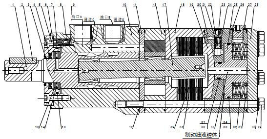
[0019] A schematic structural diagram of a hydraulic brake motor device in this embodiment is as follows: figure 1 As shown, the motor device is composed of a motor positioning and installation driving part, a motor main body engaging pair part and a motor braking device part, the motor positioning installing driving part includes parts between the output shaft 1 and the retaining ring 15, and the motor main body engaging pair part includes Rotating the stator pair 16 and the linkage shaft 17, the motor braking device part includes the parts between the brake seat 18 and the steel sheet 39.

[0020] The inside of the motor device has a structure that releases the function of the shuttle valve of the brake device. This structure is composed of two independent one-way valve functional parts, which communicate with the brake fluid cavity respectively. At the same time, the two independent one-way valve functions The components communicate with oil port A and oil port B of the mot...


PUM


Abstract

The invention relates to a hydraulic brake motor device, and belongs to the technical field of hydraulic transmission. The hydraulic brake motor device comprises a motor positioning and mounting driving part, a motor main body meshing pair part and a motor braking device part; a motor internal integrated shuttle valve is formed by combining two independent one-way valve functional components, andis radially arranged in radial direction; the two independent one-way valve functional components communicate through a brake release oil cavity to form the shuttle valve. The hydraulic brake device is quite compact in structure, small in radial section size, simple in overall structure, good in manufacturing manufacturability and good in assembling and maintaining manufacturability.

Description

technical field [0001] The invention relates to a cycloidal hydraulic motor for converting hydraulic energy to mechanical energy, in particular to a hydraulic brake motor device, which belongs to the technical field of hydraulic transmission. Background technique [0002] The hydraulic brake device has a wide range of applications, and usually adopts the normally closed brake method. Generally speaking, the hydraulic brake device used in conjunction with the cycloid hydraulic motor drive generally has a large radial size, and its brake device is mainly It consists of a friction pair composed of steel plates and friction plates, a brake oil port control piston and an elastic support body. Its structure has a large radial size and a relatively complex structure. The brake oil port is provided by an external oil circuit. Also have as Chinese patent application number is 201020295871.8, title " built-in integrated valve type brake cycloid hydraulic motor " discloses a kind of br...

Claims


Application Information

Patent Timeline
Patent Type & Authority Applications(China)
IPC IPC(8): F04C2/10F04C14/24F04C15/00F16D55/24F16D65/18F16D121/04
CPCF04C2/10F04C14/24F04C15/00F16D55/24F16D65/18F16D2121/04F16D59/02F16D55/40B60T1/062F16D2127/02
Inventor 王志生
Owner ZHENJIANG DALI HYDRAULIC MOTOR
Why Eureka
Try Eureka