Multistage delay steam injection string

A steam injection pipe string and steam injection technology, which is applied in the direction of production fluid, wellbore/well components, earthwork drilling and production, etc., can solve the problem that the steam injection volume of the oil layer unit is not easy to control, so as to improve the efficiency of steam injection and reduce the loss of heat energy , the effect of preventing damage

Active Publication Date: 2020-11-24
PETROCHINA CO LTD
View PDF4 Cites 1 Cited by
  • Summary
  • Abstract
  • Description
  • Claims
  • Application Information

AI Technical Summary

Problems solved by technology

These layered steam injection technologies are mainly realized in two ways: 1. Use the separate injection valve to realize the two-layer quantitative steam injection method of injecting upper (lower) or lower (upper) first, and the amount of steam injected in this way is better controlled , but limited to two layers of steam injection; 2. Use the throttle valve nozzle to realize simultaneous steam injection in heavy oil wells with two or more layers, because the size of the throttle valve nozzle is calculated based on the physical property parameters of the oil layer unit and steam injection parameters, etc. , the steam injection volume of each reservoir unit is not easy to control

Method used


Image

  • Multistage delay steam injection string
  • Multistage delay steam injection string
  • Multistage delay steam injection string

Examples


Embodiment Construction

[0045] In order to have a clearer understanding of the technical solutions, objectives and effects of the present invention, the specific implementation manners of the present invention will now be described with reference to the accompanying drawings.

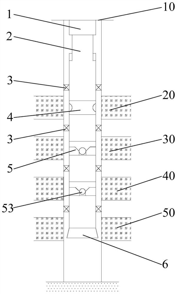
[0046] like figure 1 As shown, the present invention provides a multi-stage delayed steam injection string, which is used for steam injection to oil wells with more than three layers of oil layer units. The multi-stage delayed steam injection string includes sequentially arranged from top to bottom Delayed steam injection assembly and at least one layered steam injection assembly, specifically, when the oil well has three oil layer units, the multi-stage delayed steam injection string has a layered steam injection assembly, and when the oil well has four oil layer units , the multi-stage delayed steam injection string has two layered steam injection components, when the oil well has five reservoir units, the multi-stage delaye...


PUM


Abstract

The invention provides a multistage delay steam injection string. The multistage delay steam injection string comprises a delay steam injection assembly and at least one layered steam injection assembly which are sequentially arranged from top to bottom, wherein the delay steam injection assembly comprises a delay steam injection valve and two upper packers, the delay steam injection valve comprises an inner barrel and an outer sleeve, a steam injection annulus is formed between the outer sleeve and the inner barrel, steam inlet holes communicating with the steam injection annulus is formed inthe side wall of the inner barrel, steam outlet holes communicating with the steam injection annulus is formed in the side wall of the outer sleeve, and the steam injection annulus is filled with gelcapable of blocking the steam inlet holes and the steam outlet holes; and the layered steam injection assembly comprises a layered steam injection valve and a lower packer, the layered steam injection valve comprises a valve body, a sliding sleeve and a throwing ball, a steam injection hole are formed in the side wall of the valve body, the sliding sleeve is provided with a first position for blocking the steam injection hole and a second position for communicating the steam injection hole with the interior of the valve body, and the throwing ball can be connected with the sliding sleeve in asealed mode and enables the sliding sleeve to move from the first position to the second position. According to the multistage delay steam injection string, layered quantitative steam injection of the multi-oil-layer unit is achieved, and the steam injection efficiency of a heavy oil well is improved.

Description

technical field [0001] The invention relates to the technical field of oil production engineering, in particular to a multi-stage delayed steam injection string. Background technique [0002] In the field of heavy oil steam huff and puff in oilfields, layered steam injection technology is often used. This technology is to divide the whole well section into several steam injection units, use a group or several groups of oil layer units with similar reservoir physical properties as a steam injection unit, and separate each oil layer unit with a packer to realize one steam injection The pipe string injects steam into different oil layer units separately, so as to adjust the steam absorption profile of the oil layer unit and improve the steam injection effect. These layered steam injection technologies are mainly realized in two ways: 1. Use the separate injection valve to realize the two-layer quantitative steam injection method of injecting upper (lower) or lower (upper) firs...

Claims


Application Information

Patent Timeline
Patent Type & Authority Applications(China)
IPC IPC(8): E21B43/24E21B34/06E21B33/128
CPCE21B43/24E21B34/06E21B33/128
Inventor 张洪宝杨忠德孙振宇魏凯陈鹏程云龙王磊徐雪楠李亦缘田野胡燕刘亚洲
Owner PETROCHINA CO LTD
Why Eureka
Try Eureka