A hot and cold sprayer

A technology of cold mist and hot mist, applied in the field of sprayer, can solve the problems of complex layout of cold mist generating chamber, complicated structure of water supply mode, increase production cost, etc., and achieve the effect of avoiding hot water backflow, compact structure and saving production cost.

Active Publication Date: 2016-12-07
NVISION ELECTRICAL APPLIANCE
View PDF5 Cites 0 Cited by
  • Summary
  • Abstract
  • Description
  • Claims
  • Application Information

AI Technical Summary

Problems solved by technology

[0006] (1) Water is added from the cold mist generating chamber to the hot mist generating chamber, and the hot mist generating chamber and the cold mist generating chamber are connected through a connecting pipe. The structure of the water supply method is complex, and the phenomenon of backflow of hot water in the hot mist generating chamber is prone to occur ;
[0007] (2) The generated hot mist will enter the steam mixing chamber, and holes are opened on the side walls of the steam mixing chamber and the cold mist generating chamber, so that the cold mist generating chamber and the steam mixing chamber are connected, so that the generated cold mist can enter the In the steam mixing chamber, the mixing effect is poor;
[0008] (3) The layout of the cold mist generating chamber, the hot mist generating chamber and the water bottle in the fuselage is complicated, which makes the whole fuselage bulky and increases the production cost;
[0009] (4) The steam mixing chamber is set above the hot mist generating chamber, and its spray effect is poor

Method used


Image

  • A hot and cold sprayer
  • A hot and cold sprayer
  • A hot and cold sprayer

Examples


Embodiment Construction

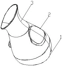
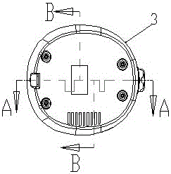
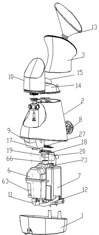
[0039] Such as Figure 1-5 As shown, the present invention discloses a cold and hot sprayer, which includes a machine base 1 , a body 2 and a spray head 3 arranged in sequence from bottom to top.

[0040] The fuselage 2 is fixed on the top of the base 1, and the top of the fuselage 2 has a cold mist outlet A4 and a hot mist outlet A5, and the fuselage 2 is equipped with a cool mist generator body 6 and a hot mist generator body 7 arranged side by side. , the side wall of the fuselage 2 has a knob switch 8, and also has a water storage chamber 9 communicated with the cold mist generator body 6 and the hot mist generator body 7, and a water tank 10 is built in the water storage chamber 9, and the water tank 10 is transparent The box body and the bottom of the water storage chamber 9 are respectively connected by a cold mist generator water inlet pipe 11 and a hot mist generator water inlet pipe 12 with the cold mist generator body 6 and the hot mist generator body 7; the nozzle ...


PUM


Abstract

The invention relates to a cold-hot spray apparatus which comprises a machine base, a machine body and a sprayer from the bottom to top in sequence, wherein the machine body is fixed above the machine base; a cold mist generator main body and a hot mist generator main body are mounted in the machine body in parallel; a water storage cavity which is communicated with the cold mist generator main body and the hot mist generator main body is formed in the side wall of the machine body; a water tank is arranged in the water storage cavity; the cold mist generator main body and the hot mist generator main body in the machine body and the water tank in the side wall of the machine body are arranged side by side like a triangle; the sprayer is tightly locked at the top of the machine body; a nozzle is arranged in the top of the sprayer; a mixing chamber is arranged in the bottom of the sprayer; the top of the mixing chamber is connected with the nozzle; the bottom of the mixing chamber is mounted at the top of the machine body. The cold-hot spray apparatus has the advantages that the mutually independent cold mist generator main body and the hot mist generator main body are used, and the water tank, the cold mist generator main body and the hot mist generator main body are arranged side by side like a triangle, so that the structure is compact, the volume of the whole spray apparatus is small and the production cost is reduced.

Description

technical field [0001] The invention relates to a nebulizer, in particular to a cold and hot nebulizer. Background technique [0002] With the improvement of people's living standards and quality of life, people pay more and more attention to health care and beauty. Now the hot and cold sprayer has become a beauty appliance product widely recognized by ordinary Chinese people. It is convenient and hygienic to use. [0003] When using the hot and cold spray device, use the hot mist alone to dilate pores and remove dirt; turn on the cold mist alone to calm and soothe the skin, balance the PH value, and replenish water, suitable for sensitive, oily, and very dry skin; turn on the cold mist at the same time And hot mist, you get a warm mist with a large amount of mist, which is suitable for any skin and feels very comfortable. [0004] In the invention patent with the patent number CN IO1607235A, a spraying device is mentioned, which includes a hot mist generating chamber, a co...

Claims


Application Information

Patent Timeline
Patent Type & Authority Patents(China)
IPC IPC(8): A61H33/06
Inventor 蒋飞
Owner NVISION ELECTRICAL APPLIANCE
Why Eureka
Try Eureka