Traction device for multi-wire-diameter array cables

A traction device and array cable technology, which is applied in the field of multi-diameter array cable traction devices, can solve the problems of loss of traction force, insufficient redundancy, and non-metallic materials that are prone to aging and brittle fracture, so as to slow down the aging speed and improve traction work efficiency , the effect of high degree of automation

Pending Publication Date: 2020-11-20
中科长城海洋信息系统有限公司
View PDF0 Cites 3 Cited by
  • Summary
  • Abstract
  • Description
  • Claims
  • Application Information

AI Technical Summary

Problems solved by technology

[0003] At present, the optical fiber sensing towed array has not yet matured to be installed on the underwater platform for application, and it is basically still in the trial trial. The array installed on the underwater platform is fixed on the side or the bow for application. No need to release and collect
The usual traction device is crawler type, generally facing a single wire diameter, and in order to be able to rotate and drive, the crawler is made of non-metallic material. On the one hand, this kind of structure is easy to slip between the array cable and lose the corresponding traction in the seawater environment. The integral type Insufficient redundancy; on the other hand, non-metallic materials are prone to aging, brittleness and fracture under the combined effects of seawater corrosion and sunlight exposure

Method used


Image

  • Traction device for multi-wire-diameter array cables
  • Traction device for multi-wire-diameter array cables
  • Traction device for multi-wire-diameter array cables

Examples


Embodiment Construction

[0030] The specific implementation manners of the present invention will be further described in detail below in conjunction with the accompanying drawings and embodiments. The following examples are used to illustrate the present invention, but are not intended to limit the scope of the present invention.

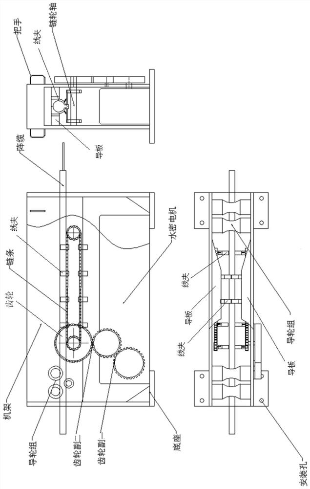
[0031] An embodiment of the present invention is a figure 1 The shown double-diameter array cable pulling device includes a base, a frame, a driving device, a transmission device, a wire clamp, and a guide plate. The driving device includes a watertight motor assembly including a reducer, gear pairs 1 and 2 gear pairs that are meshed in sequence. 2. Gears. The transmission device includes two sets of sprockets and chains. Each set of sprockets includes two parallel and opposite sprockets. The chain is located between the two parallel and opposite sprockets and is driven by the sprockets. The wheel and the gear are connected through the sprocket shaft, which is the driving...


PUM


Abstract

The invention discloses a traction device for multi-wire-diameter array cables. The traction device for the multi-wire-diameter array cables comprises a transmission device, a wire clamp and guide plates, wherein the transmission device comprises a chain wheel and a chain, a connection plate vertical to the transmission direction of the chain is arranged on the chain, and the wire clamp is arranged at the middle of the connection plate; the wire clamp comprises a left-side clamp, a right-side clamp, a spring I and a spring II; the left-side clamp and the right-side clamp are installed at the middle of the connection plate in a rotatable and bottom-bonded manner, the upper parts of the back parts of the left-side clamp and the right-side clamp are bonded with the side surfaces of the two guide plates which are located at the two sides of the wire clamp, and the distance of the middle sections of the two guide plates is the width of the wire clamp after being closed; the inner side of each of the left-side clamp and the right-side clamp comprises n arc shapes with diameters which are sequentially reduced from top to bottom, n is not less than 2, and in the closed state, n wire grooves with diameters which are sequentially reduced from top to bottom are formed. According to the traction device for the multi-wire-diameter array cables, through a plurality of the separate wire clamps and through formation for a plurality of the wire grooves in the wire clamps, traction for the array cables with many dimensions is realized.

Description

technical field [0001] The invention relates to the technical field of pulling equipment, in particular to a multi-diameter array cable pulling device. Background technique [0002] With the gradual maturity of optical fiber sensing technology, it has been applied in the field of marine communication detection in recent years. The optical fiber sensing array is composed of PU sheath tube and several sensors, and becomes a flexible array cable with a certain bending radius. When the optical fiber array is installed on the ship platform, it generally adopts the form of dragging at the tail. The optical fiber sensor array is retracted and retracted through the winch. According to the installation space and power supply and distribution needs, the position of the winch installation is usually 30m-50m away from the stern. Since the array cable is a flexible cable, after being released from the front winch, the rear end If there is no For the traction mechanism, the released arra...

Claims


Application Information

Patent Timeline
IPC IPC(8): B65H51/14B65H57/04
CPCB65H51/14B65H57/04B65H2701/32
Inventor 陶光勇李友如黄磊刘振文吴建波
Owner 中科长城海洋信息系统有限公司
Why Eureka
Try Eureka