Novel numerical control pneumatic type orthopedic tractor

A pneumatic and retractor technology, applied in non-surgical orthopedic operations, fractures, medical science, etc., can solve the problems of inability to change the traction force, and the traction force cannot be adjusted quickly and accurately, and achieve good applicability

Active Publication Date: 2020-11-20
王泽昊
View PDF19 Cites 0 Cited by
  • Summary
  • Abstract
  • Description
  • Claims
  • Application Information

AI Technical Summary

Problems solved by technology

[0004] The present invention provides a new numerically controlled pneumatic orthopedic tractor, aiming to improve the existing tractors, whose traction force cannot be changed with the patient's posture, and the traction force cannot be quickly and accurately adjusted to the required size

Method used


Image

  • Novel numerical control pneumatic type orthopedic tractor
  • Novel numerical control pneumatic type orthopedic tractor
  • Novel numerical control pneumatic type orthopedic tractor

Examples


no. 1 example

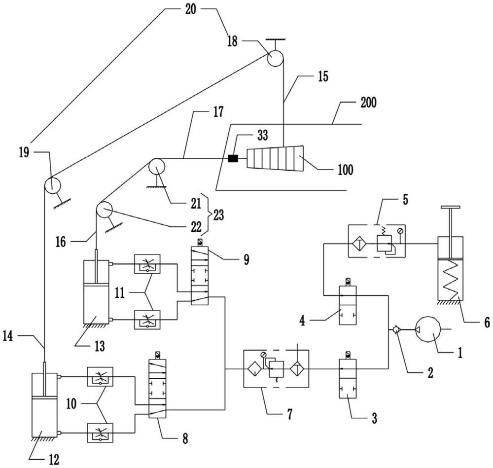
[0045] Depend on Figure 1 to Figure 4 As shown, in this embodiment, a novel numerical control pneumatic orthopedic retractor includes a main body 100 and a traction mechanism connecting the main body 100 and the affected limb 300 . Wherein, the body 100 includes a housing mechanism, an air circuit mechanism, a control mechanism, and a manipulation mechanism electrically connected to the control mechanism. The air circuit mechanism, the control mechanism, and the control mechanism are all arranged on the shell mechanism. details as follows:

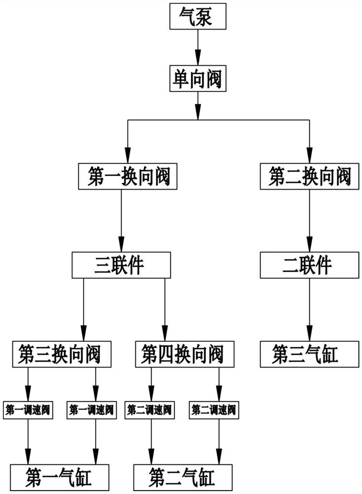
[0046] like figure 1 , image 3 and Figure 4 As shown, in this embodiment, the air circuit mechanism includes an air pump 1, a one-way valve 2, a first reversing valve 3 and a second reversing valve 4 respectively connected to the air pump 1, connected in parallel to each other and connected to the first reversing valve. The first gas path and the second gas path of the valve 3 are communicated with the third gas path of the second ...

no. 2 example

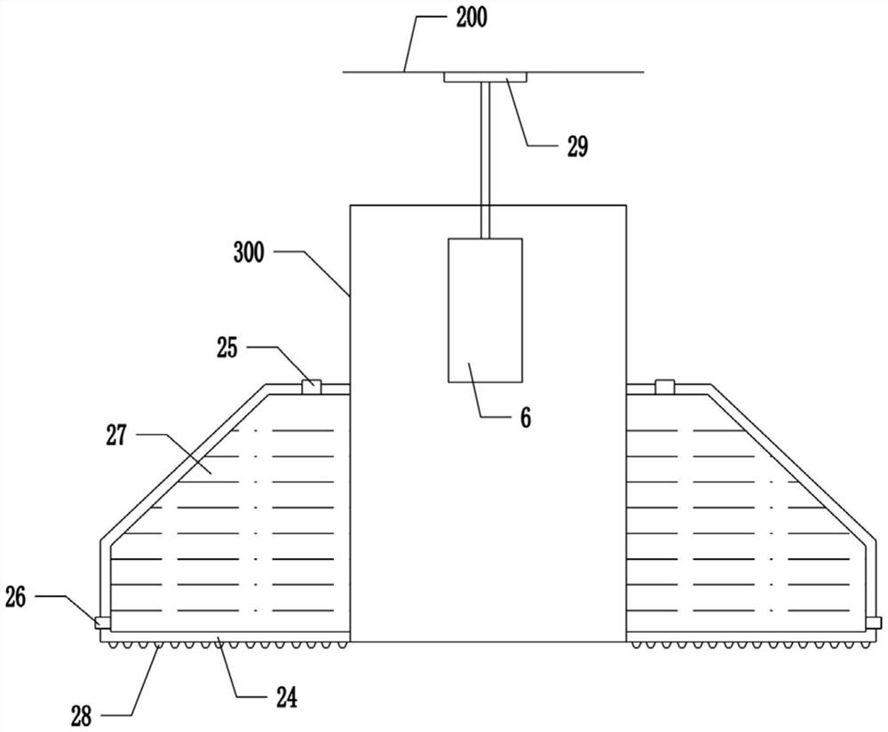
[0059] like Figure 5 As shown, in this embodiment, the output end of the third cylinder 6 is evenly distributed with three fixed claws 30, and the end surface of the fixed claws 30 is provided with an anti-skid pad 31 that abuts against the bed body 200, and the fixed claws 30 are aligned with the vertical The angle included in the directions is 20°-80°. In this embodiment, other components and structures of the retractor are the same as those in the first embodiment, and will not be repeated here. During the operation, when the output end of the third cylinder 6 moves upward, the three fixing claws 30 can be firmly locked on the bed body 200 .

no. 3 example

[0061] like Image 6As shown, in this embodiment, the body 100 further includes a suspension frame 32 for hanging on the bed body 200 , and the housing mechanism is configured on the suspension frame 32 . In the actual operation process, the shell mechanism can be fixed on the suspension frame 32 by bolts, and the suspension frame 32 is fixed on the bed body 200 in a detachable manner, so as to ensure the stability of the body 100 relative to the bed body 200 and prevent the tractor from During actual use, due to the action of the first and second pulling wires, jumping occurs.

[0062] Through the above-mentioned embodiment, the retractor of this case can control the pulling force of the first traction wire through the first speed regulating valve 10, and then control the posture of the affected limb 300, so that the affected limb 300 can be in the most comfortable suspension state, and can adapt to The needs of different patients and different affected limbs 300 parts have ...


PUM


Abstract

The present invention provides a novel numerical control pneumatic type orthopedic tractor and relates to the technical field of medical devices. The tractor comprises a body and a traction mechanismfor connecting the body and the affected limb. The body comprises an air circuit mechanism, a control mechanism and an operation and control mechanism electrically connected with the control mechanism. The air circuit mechanism comprises a first cylinder, a second cylinder and a third cylinder. The traction mechanism comprises a first traction line connecting the first cylinder with the affected limb, a second traction line connecting the second cylinder with the affected limb, and an angle sensor arranged on the second traction line. The first cylinder can drive the affected limb to hang up and down through the first traction line, and the second cylinder can tract the affected limb for treatment through the second traction line. The angle sensor can detect angles of the part where the second traction line is connected with the affected limb. The operation and control mechanism comprises a display component and an adjusting component, the display component is used for displaying information such as tension and angles of the traction lines, and the adjusting component is used for adjusting required relevant parameters.

Description

technical field [0001] The invention relates to the technical field of medical equipment, in particular to a novel numerical control pneumatic orthopedic tractor. Background technique [0002] Traction is a method of pulling the affected limb by gravity, etc., to relieve the tension and retraction of the soft tissue at the fracture or dislocation, to reset the fracture or dislocation, and achieve the purpose of treatment. Among them, skin traction to maintain the direction of bone growth is more common. [0003] In the prior art, skin traction usually uses a pulley structure to support a string of scale weights, using the weights as an external counterweight structure, using the weight of the weights to provide natural drooping tension, and applying appropriate and continuous traction to the affected limb. The fracture or dislocation of the affected limb can be restored or maintained. In the actual operation process, due to the influence of the patient's own weight and lyi...

Claims


Application Information

Patent Timeline
Patent Type & Authority Applications(China)
IPC IPC(8): A61F5/045
CPCA61F5/042
Inventor 王泽昊
Owner 王泽昊
Why Eureka
Try Eureka