
Parallel light emitting circuit

A technology for transmitting circuits and electrical signals, which is applied in the field of parallel optical transmitting circuits, can solve problems such as difficulty in ensuring high consistency of parameters of several devices, and achieve high-speed data transmission, high data rate, and high circuit integration.

Active Publication Date: 2020-11-17
XIAN MICROELECTRONICS TECH INST
View PDF7 Cites 0 Cited by
  • Summary
  • Abstract
  • Description
  • Claims
  • Application Information

AI Technical Summary

Problems solved by technology

[0005] The purpose of the present invention is to overcome the disadvantage that the parallel use of single-channel modules in the prior art is difficult to ensure the high consistency of the parameters of several devices, and to provide a parallel light emitting circuit

Method used


Image

  • Parallel light emitting circuit
  • Parallel light emitting circuit

Examples


Embodiment Construction

[0034] In order to enable those skilled in the art to better understand the solutions of the present invention, the following will clearly and completely describe the technical solutions in the embodiments of the present invention in conjunction with the drawings in the embodiments of the present invention. Obviously, the described embodiments are only It is an embodiment of a part of the present invention, but not all embodiments. Based on the embodiments of the present invention, all other embodiments obtained by persons of ordinary skill in the art without making creative efforts shall fall within the protection scope of the present invention.

[0035] It should be noted that the terms "first" and "second" in the description and claims of the present invention and the above drawings are used to distinguish similar objects, but not necessarily used to describe a specific sequence or sequence. It is to be understood that the data so used are interchangeable under appropriate ...


PUM

PropertyMeasurementUnit
emission peakaaaaaaaaaa

Abstract

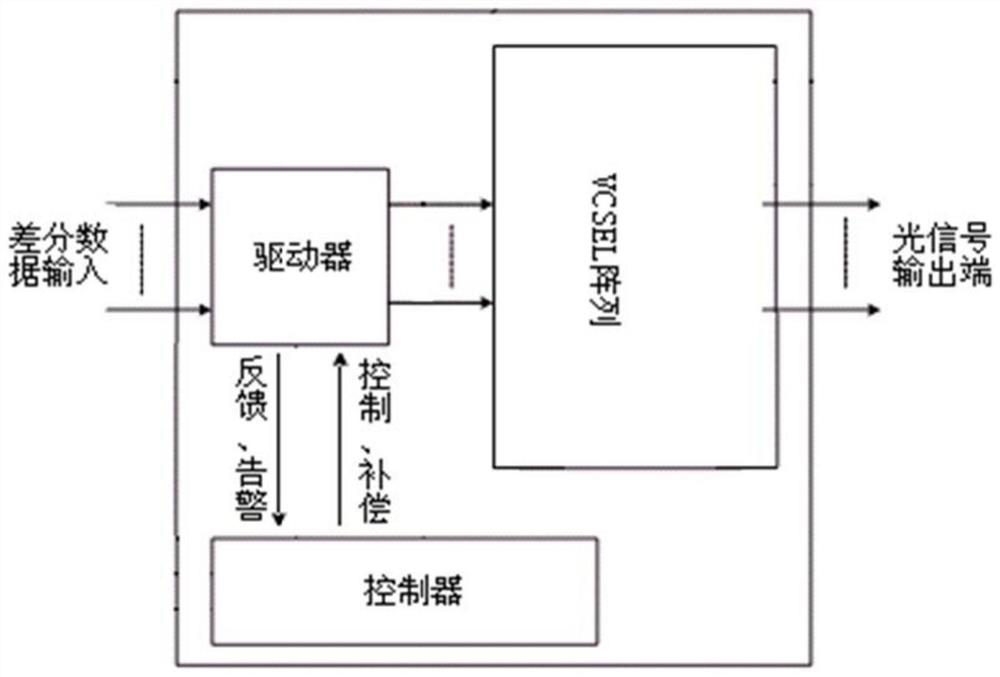
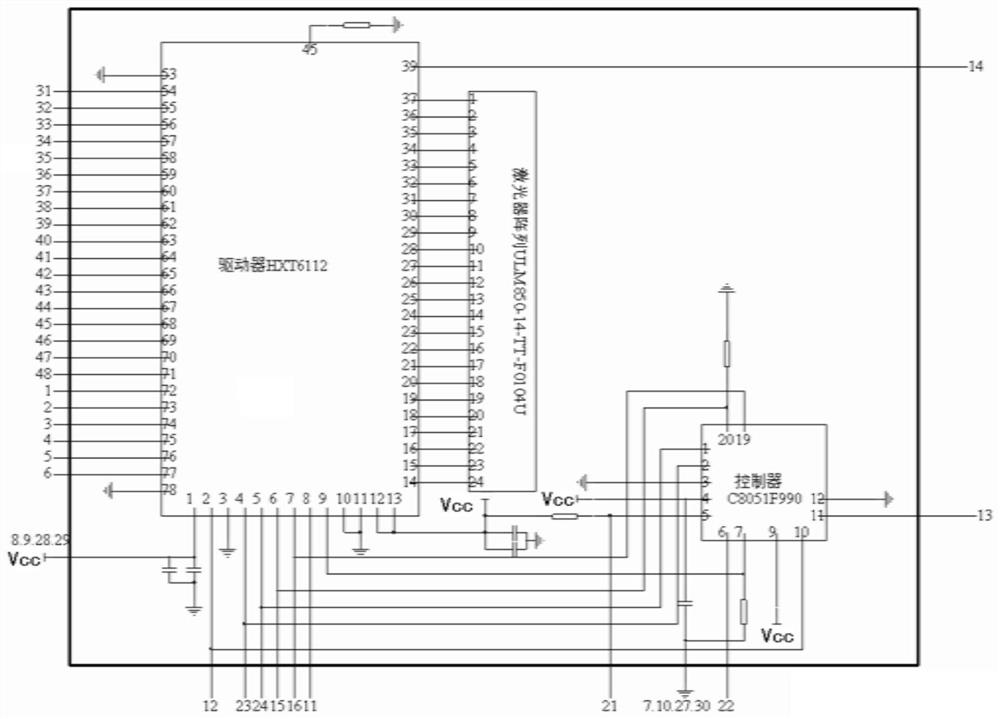
The invention discloses a parallel light emitting circuit, and belongs to the field of photoelectric digital transceiving modules. The parallel light emitting circuit comprises a microprocessor, a driver and a laser array; the microprocessor is used for sending a control instruction, receiving feedback and alarm signals of the driver and setting compensation for the driver; the driver is used fordetecting and processing the electric signal and driving the laser array; the driver is used for realizing multi-channel parallel data transmission, the driver is provided with 12 independent channels, the data transmission rate of a single channel is 10Gb / s, and each channel can work independently; and the laser array is used for emitting laser. According to the parallel light emitting circuit, the function of converting electric signals into light signals can be achieved, and high-speed data transmission with the maximum capacity of 12x10 Gb / s can be achieved by adopting a circuit structurehighly integrating the multi-path driver, the laser array and the microprocessor. The parallel light emitting circuit has the characteristics of high data rate and high line integration degree.

Description

technical field [0001] The invention belongs to the field of photoelectric digital transceiver modules, in particular to a parallel light emitting circuit. Background technique [0002] As communication technology is challenged by ever-increasing bandwidth and speed requirements, large-capacity, high-speed optical communication has become an inevitable trend in the development of the information age. Optical communication technology is a communication technology that uses light waves as the carrier and free space or waveguide as the transmission medium. Since its inception, it has been widely used in national defense, telecommunications, etc. In various military and civilian communication fields, it has become the cornerstone of modern information technology. [0003] As the core components of optical communication, the technical development of optical transceiver modules is also becoming more mature, and is gradually developing in the direction of high speed, intelligence ...

Claims


Application Information

Patent Timeline
Patent Type & Authority Applications(China)
IPC IPC(8): H04B10/50
CPCH04B10/503
Inventor 朱骏
Owner XIAN MICROELECTRONICS TECH INST
Learn More