


Quick Research
Generate reliable direction feasibility study reports for your R&D in just a few steps.

Technical Q&A
Discover and master advanced knowledge NOW. Basics, ideas, possibilities, all at once.

Find Solutions
As an expert in R&D theories, this can generate solutions to your technical problems instantly.

Evaluate Feasibility
Analyze your overall solution with one click, know your potential R&D risks in advance.

Monitor Landscape
Get weekly tech updates, stay abreast of the latest tech innovations and key insights.
Non-isoplanatic aberration correction method and device for adaptive optical line beam scanning imaging
An adaptive optics, scanning imaging technology, applied in optics, optical components, image enhancement and other directions, can solve the problems of high control complexity, high technical cost, slow imaging speed, etc. Difference correction, low cost effect
- Summary
- Abstract
- Description
- Claims
- Application Information
AI Technical Summary
Problems solved by technology
Method used
Image

Examples
Embodiment 1
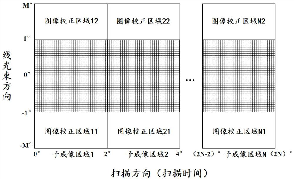
[0046] Such as figure 1 As shown, a non-isovigorated aberration correction method for adaptive optics line beam scanning imaging, the method includes: in the adaptive optics line beam scanning imaging system, performing anisotropic aberration in the line beam scanning direction Time-sharing correction and regional correction of the aberration in the non-uniform area in the direction of the line beam, specifically:
[0047] 1. Time-sharing correction of the aberration in the non-halo zone in the scanning direction of the line beam:
[0048] Step S1: According to the scanning time, divide the non-isohalo zone imaging area into multiple sub-imaging areas in the scanning direction, including sub-imaging area 1, sub-imaging area 2, ..., sub-imaging area N, and the sub-imaging area is scanning The size of the field of view in the direction does not exceed 2°; multiple sub-imaging areas can be evenly divided or non-uniformly divided; N is a positive integer, all of which meet the pr...
Embodiment 2
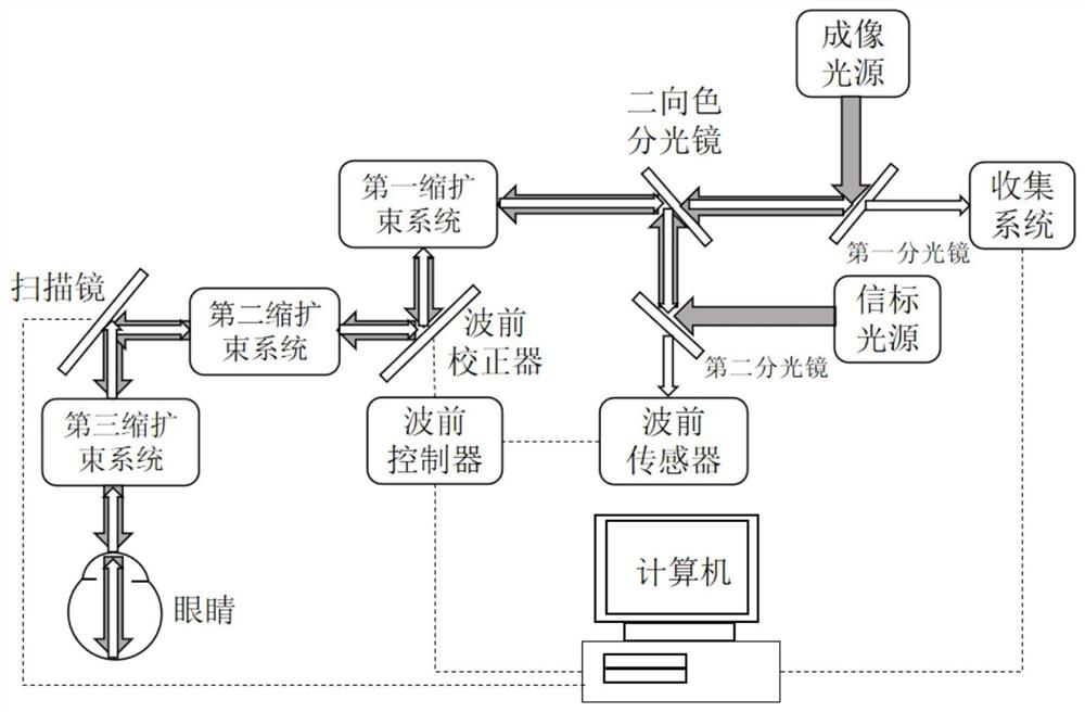
[0066] Provided is an anisotropic aberration correction device for adaptive optics line beam scanning imaging, which adopts the method of Embodiment 1 to perform anisovigorated aberration correction. In a more specific embodiment, the device includes an adaptive optical line beam scanning imaging device, a wavefront sensor, a wavefront controller, a wavefront corrector, and a computer;
[0067] The wavefront controller extracts the wavefront aberration measured by the wavefront sensor, and feeds back to control the wavefront corrector, and the computer controls the wavefront controller according to the method of Embodiment 1 to complete the closed-loop correction and realization of the non-uniform area image difference. Differential area correction of non-isovigorated images in online or offline form.
[0068] refer to figure 2 , in a preferred embodiment, the adaptive optics line beam scanning imaging device includes an imaging light source, a collection system, a first bea...
Embodiment 3
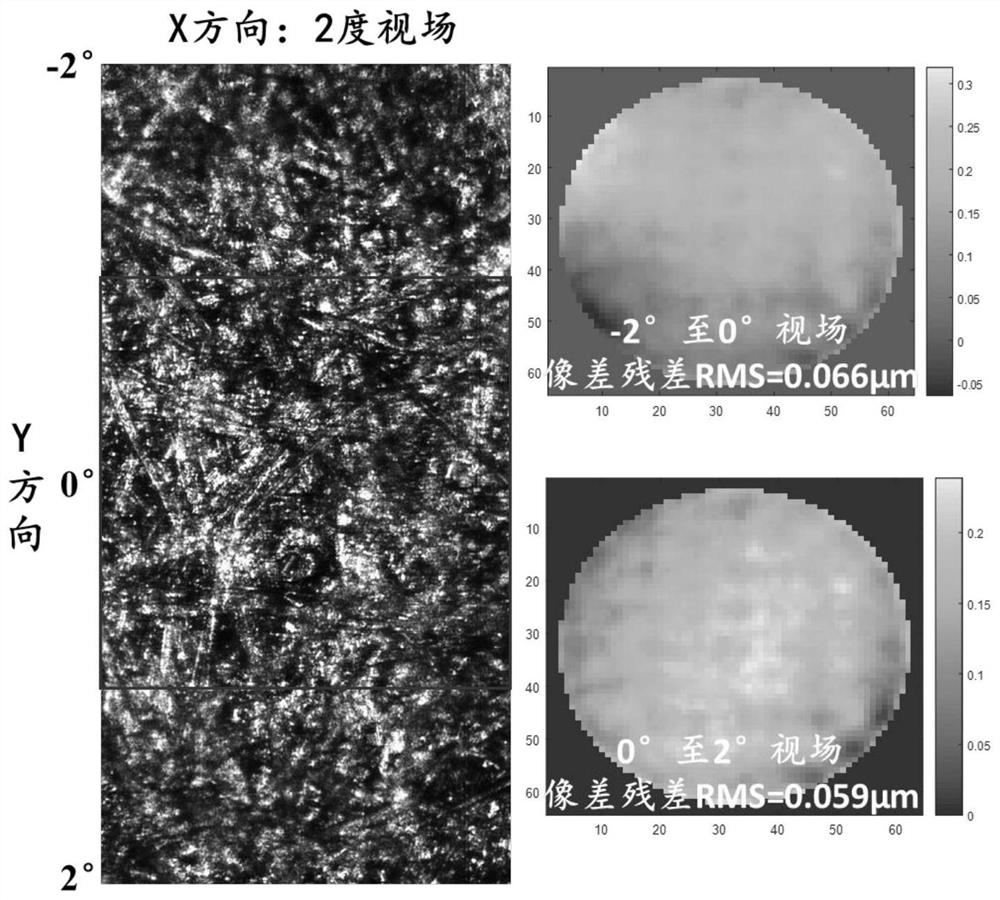
[0073] Embodiment 3 carries out the comparison of conventional correction method and the method of the present invention
[0074] refer to image 3 , is the conventional single-shot adaptive optics aberration correction result. Among them, the imaging field of view is 2 degrees (scanning direction)*4 degrees (line beam direction). After a single aberration correction is performed on the entire imaging field of view, only the center 2*2 degrees belongs to the iso-halo zone, and the aberration of the field of view It is completely corrected, and the aberrations of the fields of view on both sides are not completely corrected, and are relatively blurred; the corresponding two sub-region wavefront aberration data (measured by the Hartmann wavefront sensor) are also visible, and the aberration residuals exceed the requirements of the diffraction limit (λ / 14, λ=795nm).
[0075] refer to Figure 4 , is the result obtained by the method of the present invention. Among them, image...
PUM
 Abstract
Description
Claims
Application Information
 - R&D Engineer
- R&D Manager
- IP Professional
- Industry Leading Data Capabilities
- Powerful AI technology
- Patent DNA Extraction
Browse by: Latest US Patents, China's latest patents, Technical Efficacy Thesaurus, Application Domain, Technology Topic, Popular Technical Reports.
© 2024 PatSnap. All rights reserved.Legal|Privacy policy|Modern Slavery Act Transparency Statement|Sitemap|About US| Contact US: help@patsnap.com