Thick ore layer layered filling mining test device and test method
A test device and a technology of ore bed, applied in the field of civil engineering test equipment, can solve problems such as variable stiffness
- Summary
- Abstract
- Description
- Claims
- Application Information
AI Technical Summary
Problems solved by technology
Method used
Image


Examples
Embodiment 1
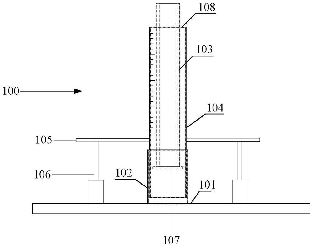
[0105] Such as figure 1 As shown, a variable stiffness simulation device includes: a sleeve assembly 100, a stiffness adjustment assembly 200, a spring fastening assembly 300, a clamp holding force device 400, and a miniature rod-type displacement sensor 500;
[0106] The casing assembly 100 includes: a base 101, a bottom casing 102, a loading casing 103, a casing casing 104, a casing casing annular disk 105, a casing casing lifting assembly 106, and a rigid plate 107;
[0107] Wherein, the bottom end of the bottom sleeve 102 is fixedly connected to the top surface of the base 101;
[0108] Wherein, the casing sleeve 104 is inserted into the bottom casing 102, and the outer surface of the casing casing 104 is adapted to the inner surface of the bottom casing 102, and the setting of the bottom casing 102 is used to ensure that the casing casing is in the Vertical state; the lower end region of the shell sleeve 104 is fixed with a shell sleeve annular disk 105, the bottom fixe...
Embodiment 2
[0187] Embodiment 2: The purpose of embodiment 2 is in order to study a kind of mineral filling mining test test device. Its biggest feature is that the stiffness needs to be changed during the test.
[0188] The equipment in Example 1 cannot achieve changes in stiffness during the test, and it cannot meet the requirements of the mineral filling mining test.
[0189] To this end, the following improvements are made:
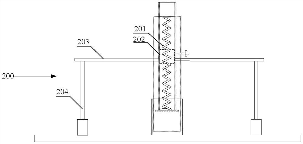
[0190] The "stiffness adjustment assembly 200, spring fastening assembly 300" of Embodiment 1 constitutes a spring end adjustment assembly; as Figure 13 As shown, the device is provided with a plurality of spring end adjustment components along the vertical direction of the shell sleeve; a miniature rod type displacement sensor 500 is provided on the rigid plate 107 and the lowermost steel cylinder horizontal rod 203, or, on the base The bottom of the rigid board is provided with a rigid plate displacement sensor (for example: ultrasonic ranging sensor, infrare...
Embodiment 3
[0219] Embodiment 3: as Figure 14 As shown, the width of the collet plate is smaller than the diameter of the spring, which is taken as 1 / 4 to 1 / 8 of the diameter of the spring; and the two corresponding collet plates pass through the central axis of the spring;
[0220] That is to say, embodiment 3 has provided the application mode of the present application, and it when simulating variable stiffness, the stiffness of simulation is some "scattered points" (the height of steel cylinder is also some specific values), rather than continuous stiffness, that is, as Figure 15-16 As shown, there are only two state diagrams (one collet plate can pass through the pitch of the coil spring).
[0221] The design of embodiment 3 is more practical when used.
[0222] Further, the front side of the chuck plate is adapted to the spatial position of the coil spring, that is, a small section of spiral protrusion is also set on the front side of the chuck plate (use the protrusion to compres...
PUM
 Abstract
Description
Claims
Application Information
 - R&D
- Intellectual Property
- Life Sciences
- Materials
- Tech Scout
- Unparalleled Data Quality
- Higher Quality Content
- 60% Fewer Hallucinations
Browse by: Latest US Patents, China's latest patents, Technical Efficacy Thesaurus, Application Domain, Technology Topic, Popular Technical Reports.
© 2025 PatSnap. All rights reserved.Legal|Privacy policy|Modern Slavery Act Transparency Statement|Sitemap|About US| Contact US: help@patsnap.com