Shock absorber piston assembly and self-adjusting damping shock absorber comprising same
A piston assembly and automatic adjustment technology, which is applied in the direction of shock absorbers, springs/shock absorbers, shock absorbers, etc., can solve the problems of affecting the shock absorption effect, unadjustable damping, and high cost, so as to facilitate popularization and use and reduce processing Difficulty, the effect of reducing production costs
- Summary
- Abstract
- Description
- Claims
- Application Information
AI Technical Summary
Problems solved by technology
Method used
Image
Examples
Embodiment 1
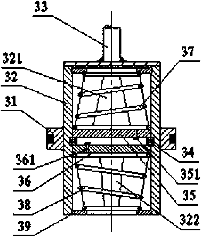
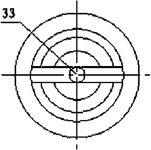
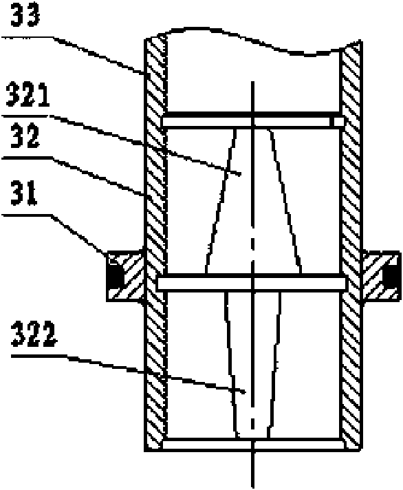
[0034] Figure 1 ~ Figure 2 Disclosed in is a shock absorber piston assembly, which is mainly composed of a main piston 31, an auxiliary working cylinder 32 and a floating piston, the inner hole of the main piston 31 is fixedly connected with the outer circle of the auxiliary working cylinder 32, and the outer circle of the auxiliary working cylinder 32 One end is fixedly connected with a piston rod 33, and a snap ring 34, a floating piston, a floating piston return spring, and a spring seat 39 are respectively installed in the auxiliary working cylinder 32, and a throttling valve is arranged on the inner cylinder wall of the auxiliary working cylinder 32 in the axial direction. Groove, the cross-sectional area of the throttling groove changes gradually, that is, its longitudinal cross-sectional shape is a trapezoidal structure.
[0035] The above-mentioned floating piston is composed of a compression floating piston 35 and a recovery floating piston 36 installed at both ends...
Embodiment 2
[0042] Figure 7 Disclosed in is another shock absorber piston assembly, which has the function of automatically adjusting damping only in the recovery stroke. The basic structure of the piston assembly is the same as that of Embodiment 1. The working cylinder 32 is composed of a floating piston, the difference is that the compression stroke assembly is cancelled, so that the structure is simpler and the production cost is lower, that is, the floating piston is a recovery floating piston 36 with a check valve B361, The floating piston return spring is a return floating piston return spring 38, and the throttling groove is a return throttling groove 322, and the longitudinal section shape of the restoration throttling groove 322 is a trapezoidal structure with a large top and a small bottom.
[0043] As a modification of the second embodiment, the longitudinal cross-sectional shape of the restoration throttle groove 322 may also be a multi-level stepped structure, that is, the ...
Embodiment 3
[0045] Figure 8 Disclosed in is a double-barrel type automatic adjustment damping shock absorber containing a shock absorber piston assembly. The shock absorber includes an oil storage cylinder 1, a working cylinder 2, a piston assembly 3 and an elastic element connected to the frame. The piston described above is the shock absorber piston assembly 3 described in Embodiment 1. The outer circle of the main piston 31 of the shock absorber piston assembly 3 is in sliding fit with the inner cylinder wall of the working cylinder 2, and the piston rod 33 extends out of the working cylinder 2. And connect with frame.
[0046] The shock absorber piston assembly 3 is mainly composed of a main piston 31, an auxiliary working cylinder 32 and a floating piston, the inner hole of the main piston 31 is fixedly connected with the outer circle of the auxiliary working cylinder 32, and one end of the auxiliary working cylinder 32 is fixedly connected with a The piston rod 33 and the auxiliar...
PUM
 Abstract
Description
Claims
Application Information
 - R&D
- Intellectual Property
- Life Sciences
- Materials
- Tech Scout
- Unparalleled Data Quality
- Higher Quality Content
- 60% Fewer Hallucinations
Browse by: Latest US Patents, China's latest patents, Technical Efficacy Thesaurus, Application Domain, Technology Topic, Popular Technical Reports.
© 2025 PatSnap. All rights reserved.Legal|Privacy policy|Modern Slavery Act Transparency Statement|Sitemap|About US| Contact US: help@patsnap.com


