
Selection method for determining test stress corresponding to test load during spring prestressing treatment

A technology for testing stress and load. It is used in special data processing applications, electrical digital data processing, instruments, etc., and can solve problems such as high stress, small winding ratio, and large deformation.

Pending Publication Date: 2020-11-13
无锡金峰园弹簧制造有限公司
View PDF0 Cites 0 Cited by
  • Summary
  • Abstract
  • Description
  • Claims
  • Application Information

AI Technical Summary

Problems solved by technology

[0002] Under normal circumstances, the test stress of the given parameters and selected materials of the ideal pattern design should not exceed 680MPa~930MPa, and the hardness is in the range of HRC45~HRC50. Rigid requirements, usually designed springs are of small winding ratio, large deformation, high stress, so when checking the spring pattern, it can be found that the maximum working stress corresponding to the maximum working load of the spring all exceeds the test stress of 680MPa ~ 930MPa, while The test load of the spring is equal to or greater than the maximum working load of the spring, and the spring requires strong pressure treatment. Therefore, how to determine a test stress value corresponding to the test load under the premise of meeting the customer's target life spring is an urgent need in this technical field. technical issues to be resolved

Method used


Image

  • Selection method for determining test stress corresponding to test load during spring prestressing treatment
  • Selection method for determining test stress corresponding to test load during spring prestressing treatment
  • Selection method for determining test stress corresponding to test load during spring prestressing treatment

Examples


Embodiment 1

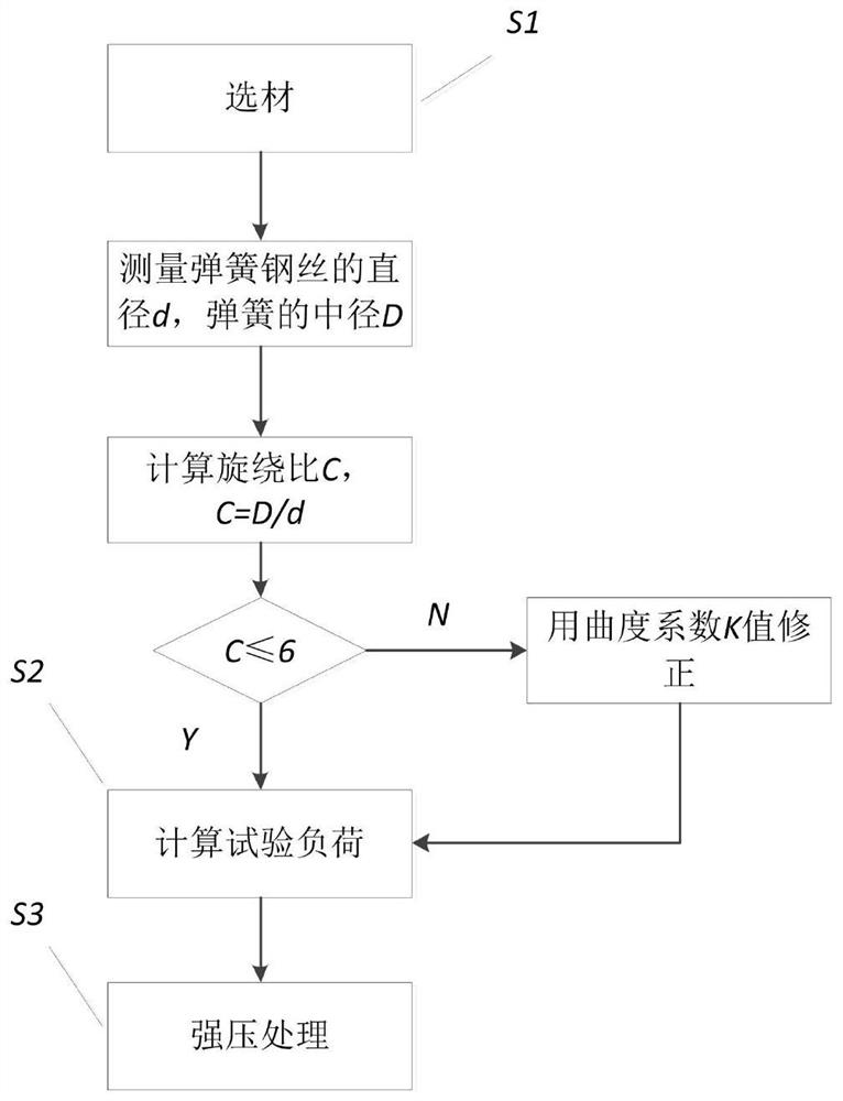
[0047] A method for determining the test stress corresponding to the test load during the spring pressure treatment, including the following steps:

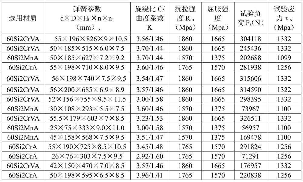
[0048] Step S1: Material selection; spring steel made of 60Si2MnA material is selected; spring steel wire made of 60Si2MnA material is measured to be 50mm, the middle diameter of the spring is 185mm, and the winding ratio

[0049] Step S2: Calculate the test load; set the test load as F s , The test stress of spring steel of different materials is τ s , Τ s According to calculation formula (1) or calculation formula (2); according to design requirements, the tensile strength of spring steel made of 60Si2MnA is 1570Mpa, and the yield strength of spring steel made of 60Si2MnA is 1375Mpa.

[0050] Calculation formula (1)τ s Tensile strength R according to design requirements m 70% of the lower limit is calculated and determined:

[0051] τ s =0.7σ b =0.7×1570=1099Mpa (1);

[0052] Or, the calculation formula (2)τ s 80% of the yield strength ...

Embodiment 2

[0062] A method for determining the test stress corresponding to the test load during the spring pressure treatment, including the following steps:

[0063] Step S1: Material selection; spring steel made of 60Si2CrA is selected; spring steel wire made of 60Si2CrA is measured to be 55mm, the middle diameter of the spring is 198mm, and the winding ratio

[0064] Step S2: Calculate the test load; set the test load as F s , The test stress of spring steel of different materials is τ s , Τ s According to calculation formula (1) or calculation formula (2); according to design requirements, the tensile strength of spring steel made of 60Si2CrA is 1765Mpa, and the yield strength of spring steel made of 60Si2CrA is 1570Mpa.

[0065] Calculation formula (1)τ s Tensile strength R according to design requirements m 70% of the lower limit is calculated and determined:

[0066] τ s =0.7σ b =0.7×1765=1235.5Mpa (1);

[0067] Or, the calculation formula (2)τ s 80% of the yield strength required by spri...

Embodiment 3

[0077] A method for determining the test stress corresponding to the test load during the spring pressure treatment, including the following steps:

[0078] Step S1: Material selection; use spring steel made of 60Si2CrVA material; measure the spring steel wire made of 60Si2CrVA material to be 55mm, the middle diameter of the spring is 196mm, and the winding ratio

[0079] Step S2: Calculate the test load; set the test load as F s , The test stress of spring steel of different materials is τ s , Τ s According to calculation formula (1) or calculation formula (2); according to design requirements, the tensile strength of spring steel made of 60Si2CrVA is 1860Mpa, and the yield strength of spring steel made of 60Si2CrVA is 1665Mpa.

[0080] Calculation formula (1)τ s Tensile strength R according to design requirements m 70% of the lower limit is calculated and determined:

[0081] τ s =0.7σ b =0.7×1860=1302Mpa (1);

[0082] Or, the calculation formula (2)τ s 80% of the yield strength requ...


PUM

PropertyMeasurementUnit
Middle diameteraaaaaaaaaa
Tensile strengthaaaaaaaaaa
Yield strengthaaaaaaaaaa

Abstract

The invention relates to a selection method for determining test stress corresponding to a test load during spring prestressing treatment. The selection method comprises the following steps: S1, selecting materials including selecting spring steel made of three materials, namely 60Si2MnA, 60Si2CrA and 60Si2CrVA; S2, calculating a test load including setting a test load as Fs and spring steel teststresses of different materials as tau s, and calculating according to a calculation formula (1) or a calculation formula (2), wherein the calculation formula (1) is calculated and determined according to 70% of the lower limit value of the tensile strength required by the design: tau s = 0.7 sigma b (1), or the calculation formula (2) is as follows: tau s is equal to 0.8 sigma s (2) according to80% of the yield strength required by the spring steel design; taking a larger value of results obtained in the calculation formula (1) and the calculation formula (2); calculating the test load according to a calculation formula (3); S3, carrying out prestressing treatment under the condition that the test stresses corresponding to the three materials of 60Si2MnA, 60Si2CrA and 60Si2CrVA are addedwith 5% of test load or the deformation of 3mm of the spring. Product reliability is improved.

Description

Technical field [0001] The invention relates to the technical field of determining the test stress of a hot-wound cylindrical helical compression spring, in particular to a method for determining the test stress corresponding to the test load when the spring is stressed. Background technique [0002] Under normal circumstances, the test stress given by the parameters and selected materials of the ideal pattern design should not exceed 680MPa~930MPa, and the hardness should be within the range of HRC45~HRC50. However, the engineering machinery springs involved at present are limited due to their structural size limitations and load characteristics. Hard requirements, usually designed springs are of small winding ratio, large deformation, high stress, so when checking the spring pattern, it can be found that the maximum working stress corresponding to the maximum working load of the spring all exceeds the test stress 680MPa~930MPa, and The spring test load is equal to or greater th...

Claims


Application Information

Patent Timeline
IPC IPC(8): G06F30/17G06F30/20G06F119/04G06F119/14
CPCG06F30/17G06F30/20G06F2119/14G06F2119/04
Inventor 袁金戈蓝俊张建平刘镇玮孙晖
Owner 无锡金峰园弹簧制造有限公司
Learn More