
Reusable universal radio frequency device test fixture

A technology of radio frequency devices and test fixtures, which is applied to parts, instruments, and measuring devices of electrical measuring instruments. It can solve the problems of complex testing process, poor compatibility of test fixtures, and high cost, and achieve a wide range of applications. No effect of mechanical loss

Pending Publication Date: 2020-11-13
QINGDAO UNIV
View PDF6 Cites 0 Cited by
  • Summary
  • Abstract
  • Description
  • Claims
  • Application Information

AI Technical Summary

Problems solved by technology

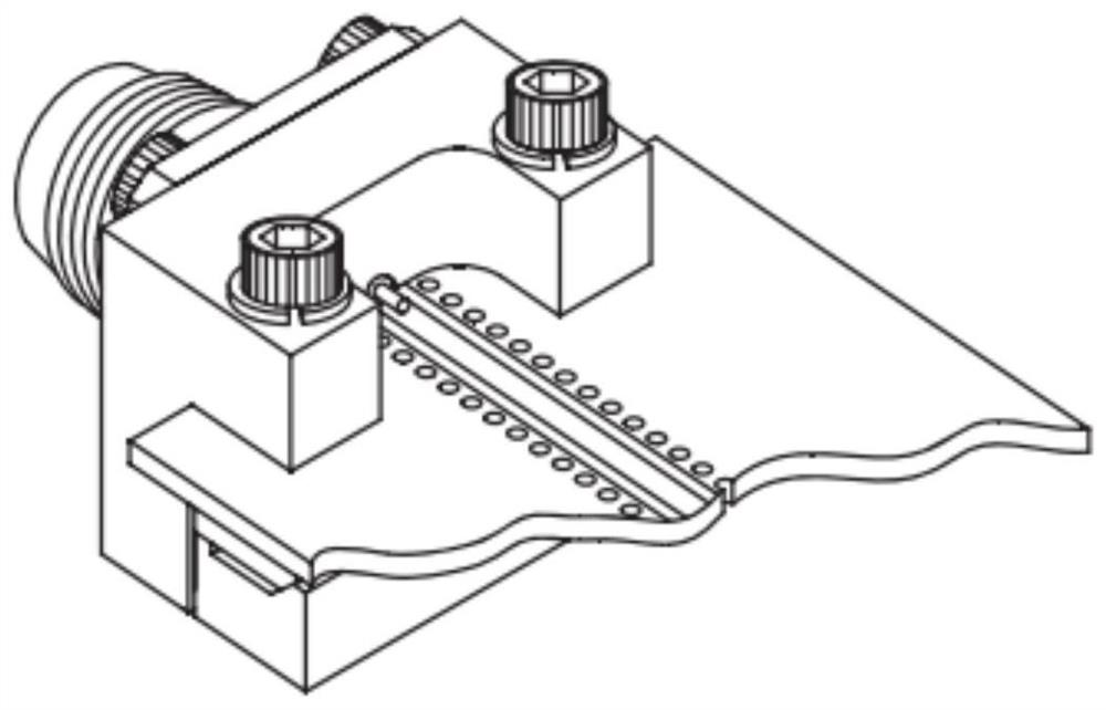
Existing technical solutions such as image 3 and Figure 4 As shown, the RF device to be tested first needs to drill screw holes, which can be fixed with the screws on the device. Although the fixing effect is good, the test process is complicated and requires special drilling and fixing. It is not suitable to use glass and silicon. RF Device Testing Fabricated on Substrates
Most of the existing test fixtures are imported and expensive
Although it has good compatibility and can be applied to the application scenarios of various external dimensions and multi-port RF device testing, but the form of slide rails or positioning holes is often used, or it does not have the disadvantages of reusability (no welding required)
[0004] Therefore, the existing test fixture has the following problems: (1) can not realize repeatable utilization, can not be compatible with the measurement of the radio frequency device of different port number and position, as one-port antenna, two-port filter, three-port power divider, four-port Measurement tasks of RF devices such as port couplers; (2) Most of them are imported products with high cost and poor compatibility of test fixtures, which cannot be reused and virtually increase the test cost of enterprises; (3) rely on spring pressing, slide rail physical Contact and other methods cannot achieve good contact between the signal of the RF device under test and the signal of the test fixture, reducing the measurement accuracy

Method used


Image

  • Reusable universal radio frequency device test fixture
  • Reusable universal radio frequency device test fixture
  • Reusable universal radio frequency device test fixture

Examples


Embodiment 1

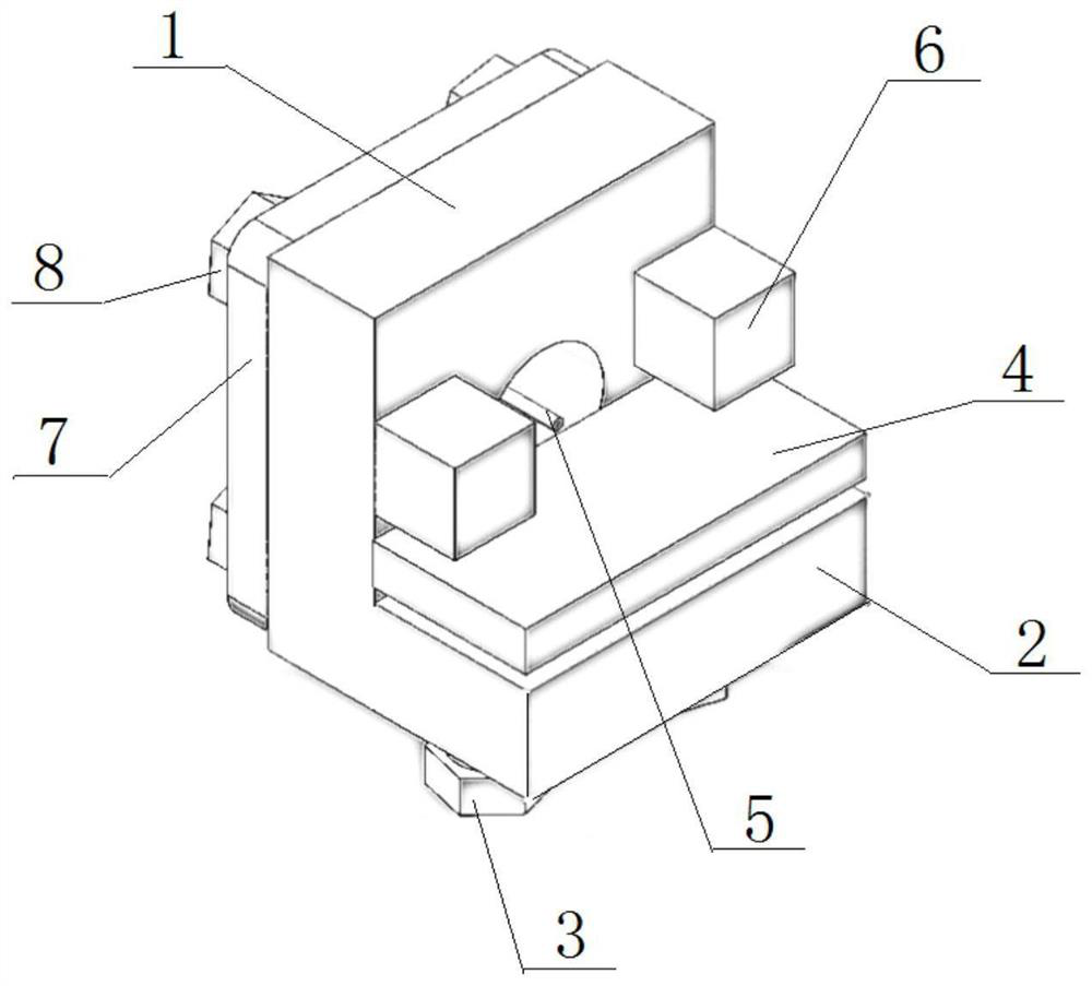
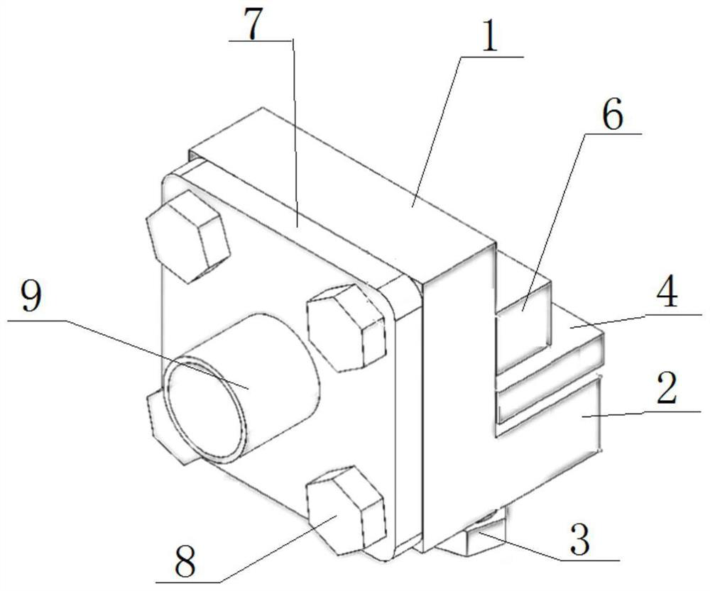
[0028] Such as Figure 1 to Figure 2 As shown, the reusable universal radio frequency device test fixture of the present invention includes a single-ended SMA connector connected to the radio frequency device to be tested, and a base for fixing the single-ended SMA connector, the base includes an integrally processed vertical plate 1, and The base plate 2 installed perpendicular to the bottom of the vertical plate 1; the bottom surface of the base plate 2 is equipped with a number of through-setting adjusting bolts 3, and the top of the adjusting bolts 3 can lift up an adjusting plate 4; the center of the vertical plate 1 is provided with a through hole, along which the The single-ended SMA connector set in the direction of the hole is fixed on the back of the vertical plate 1, and the single-ended SMA connector includes a tubular shell 9, which is fixed on the vertical plate 1 via the positioning plate 7, and the inside of the tubular shell 9 is installed with the radio freque...

Embodiment 2

[0040] As an improvement of the present invention, it is possible to test and replace the single-ended SMA connectors as needed.

[0041] The base plate 2 has two adjusting bolts 3 for screwing into the base plate 2 to control the height of the adjusting plate 4 .

[0042] The material of the regulating plate 4 is a metal material with good electrical conductivity, such as copper, aluminum alloy, stainless steel and other metals.

[0043] After the radio frequency device to be tested is put into the card slot of the base, the metal core 5 in the center of the single-ended SMA connector, the radio frequency device to be tested, the adjustment plate 4, and the adjustment bolt 3 are in sequence from top to bottom.

[0044] There are two adjusting bolts 3 and the number of adjusting bolts 3 .

[0045] The measurement fixture includes a single-ended SMA connector and a coplanar waveguide (CPW) structure base. The base is followed by an adjustment plate 4, a limit block 6, and a po...


PUM


Abstract

The invention relates to a reusable universal radio frequency device test fixture, and belongs to the technical field of radio frequency device measurement. The test fixture comprises a single-end SMAconnector and a base for fixing the single-end SMA connector, and the base comprises a vertical plate and a bottom plate installed perpendicular to the bottom of the vertical plate; a plurality of through adjusting bolts are mounted on the bottom surface of the bottom plate, and an adjusting plate is movably jacked up from the tops of the adjusting bolts; a through hole is formed in the center ofthe vertical plate, a single-end SMA connector arranged in the direction of the through hole is fixed to the back of the vertical plate through a positioning plate, a metal core making contact with aradio frequency device to be tested is installed in the single-end SMA connector, and the metal core horizontally penetrates through the back of the vertical plate and extends to the position above the adjusting plate; a to-be-tested radio frequency device is clamped to the adjusting plate jacked by the adjusting bolts and is fixedly installed in a clamping groove formed between limiting blocks fixedly installed on the two sides of the through hole of the vertical plate. The test fixture can be used for measuring high-frequency devices with various external dimensions, has the characteristicsof reusability and no need of welding, and can be widely applied to radio frequency device measurement occasions.

Description

technical field [0001] The invention relates to a reusable universal radio frequency device test fixture, which belongs to the technical field of radio frequency device measurement. Background technique [0002] RF devices are the core of the front-end of wireless communication systems, including filters, duplexers, couplers, switches, antennas, etc. During the test, the radio frequency device is connected to the test instrument through the test fixture, and the relevant parameter indicators are read from the test instrument. [0003] The traditional method uses gold-tin solder to solder the single-ended SMA connector on the PCB signal transmission line equipped with the RF device to be tested. The use of gold-tin solder not only reduces the measurement accuracy of the RF device, but also the single-ended SMA connector cannot be reused. Existing technical solutions such as image 3 and Figure 4 As shown, the RF device to be tested first needs to drill screw holes, which c...

Claims


Application Information

Patent Timeline
Patent Type & Authority Applications(China)
IPC IPC(8): G01R1/04
CPCG01R1/0425
Inventor 姚钊张伟张杰李家民吕鲁豫
Owner QINGDAO UNIV
Learn More