Direct-current ore-smelting electric furnace with variable loop

A submerged heat electric furnace and circuit technology, which is applied in the direction of electric furnace heating, furnace, furnace components, etc., can solve the problems of severe anode heating at the end, fast consumption of anode electrodes, and large heat generation, so as to prevent accumulation and agglomeration and speed up Thermal fusion, the effect of increasing the degree of contact

Active Publication Date: 2020-11-13
贵州金源锰业股份有限公司
View PDF6 Cites 0 Cited by
  • Summary
  • Abstract
  • Description
  • Claims
  • Application Information

AI Technical Summary

Problems solved by technology

[0006] In order to make up for the deficiencies of the prior art, the present invention proposes a variable circuit direct-current submerged thermal electric furnace. The present invention is mainly used to solve the problem that the heating value of the anode area of ​​the positive electrode is higher than that of the negative electrode cathode during the working process of the current submerged thermal electric furnace. The calorific value of the area is large, and the smelting current is the main source of heat energy for electrode roasting. The roasting near the electrode holder is similar under the condition of equal pressure and release speed, but because the anode electrode is consumed relatively quickly, and the heating of the anode is more serious at the end, it often occurs The problem of soft and hard break accidents of electrodes

Method used


Image

  • Direct-current ore-smelting electric furnace with variable loop
  • Direct-current ore-smelting electric furnace with variable loop
  • Direct-current ore-smelting electric furnace with variable loop

Examples


Embodiment Construction

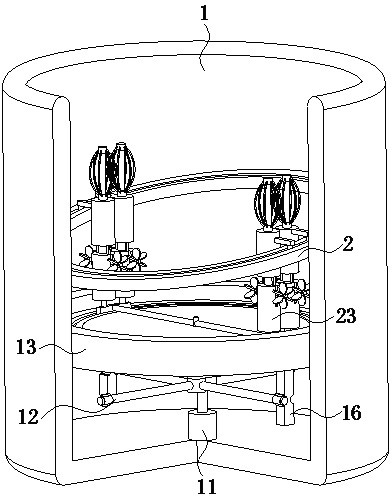
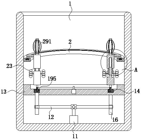
[0029] use Figure 1-Figure 5 A DC submerged arc furnace with a variable circuit according to an embodiment of the present invention is described as follows.

[0030] Such as Figure 1-Figure 5 As shown, a DC submerged arc furnace with a variable circuit according to the present invention includes a furnace body 1; the inner surface of the furnace body 1 is fixedly connected with a servo motor 11 at the bottom of the furnace body 1, and the servo motor 11 is connected to the furnace body through a wire. The controller is electrically connected; the drive shaft of the servo motor 11 is fixedly connected with conductive columns 12 arranged uniformly, and the number of conductive columns 12 is four; the electrodes of the left and right conductive columns 12 are negative poles and positive poles respectively; the front and rear conductive columns The electrodes of 12 are negative pole and positive pole respectively; The said conducting column 12 of each positive pole is all elect...


PUM


Abstract

The invention belongs to the technical field of direct-current ore-smelting electric furnaces, in particular to a direct-current ore-smelting electric furnace with a variable loop. The direct-currentore-smelting electric furnace comprises a furnace body; the inner surface of the furnace body is fixedly connected with a servo motor at the bottom of the furnace body, and the servo motor is electrically connected with a controller through a wire; four uniformly-arranged conduction columns are fixedly connected to a drive shaft of the servo motor; the electrodes of the left and right conduction columns are a negative electrode and a positive electrode respectively; the electrodes of the front and rear conduction columns are a negative electrode and a positive electrode respectively; and electrode disks which are uniformly arranged are fixedly connected in the inner wall of the supporting plate. The direct-current ore-smelting electric furnace is mainly used for solving the problems that in the working process of an existing ore-smelting electric furnace, the calorific value of a positive electrode anode area is larger than that of a negative electrode cathode area, smelting current isa main heat energy source for electrode roasting, roasting near an electrode holder is similar under the condition that the pressing-down speed is equal, and but due to the fact that anode electrodeconsumption is relatively high and heating of the anode by an end head is more serious, and soft and hard electrode breakage accidents often occur.

Description

technical field [0001] The invention belongs to the technical field of direct current submerged heat electric furnace, in particular to a variable circuit direct current submerged heat electric furnace. Background technique [0002] At present, due to the lack of vertical positive and negative electrode smelting technologies in industrial applications, some related smelting technologies are still in the process of exploration, but this furnace type has achieved initial results in the existing very rare production lines, and the advantages of energy saving and environmental protection are obvious. , Compared with the AC electric furnace, it has the advantages of high power factor, small short-circuit reactance, no skin effect, etc., good powder adaptability, and stable production furnace conditions; compared with the bottom electrode technology DC furnace, there is no bottom electrode consumption, so there is no need to do it Regular bottom electrode overhaul work can ensure ...

Claims


Application Information

Patent Timeline
Patent Type & Authority Applications(China)
IPC IPC(8): F27D11/10
CPCF27D11/10
Inventor 易江萍杜昌红罗胜龙张元
Owner 贵州金源锰业股份有限公司
Why Eureka
Try Eureka