Energy-saving tunnel advanced small conduit quick-installed slurry-stopping structure

An advanced small conduit and energy-saving technology, which is applied in tunnels, tunnel linings, shaft equipment, etc., can solve problems such as violations, prolonging the construction cycle of tunnels, and failure of filling materials to form, and achieve the effect of firm and stable connections

Active Publication Date: 2022-04-01
CHINA RAILWAY FIRST GRP CO LTD +1
View PDF13 Cites 0 Cited by
  • Summary
  • Abstract
  • Description
  • Claims
  • Application Information

AI Technical Summary

Problems solved by technology

[0003] Usually the tunnel is constructed with a small conduit in advance, and the gap between the borehole wall and the outer wall of the small conduit is sealed with cement mortar, anchoring agent, expansion cement, etc. After -60min, when it can withstand the specified maximum grouting pressure and water pressure, use high-pressure grouting pump to grout. The grouting can be terminated in 15min-20min, and the nozzle of the small grouting conduit is blocked to prevent the grout from flowing back out of the pipe. This method has many disadvantages: First, the solidification time of the filler is 30min-60min, which prolongs the tunnel construction cycle time, which violates the principle of "quick support and early closure" in tunnel construction; secondly, because the material of the filling is different from that of the surrounding rock of the tunnel, the filling is hard material, and the filling shrinks during the solidification process, which may easily cause thirdly, the tunnel is constructed underground, and there is mostly groundwater in the surrounding rock of the tunnel, and there is seepage or even strands of water flowing out of the borehole, and the filling is affected by the disturbance intensity of the groundwater during the filling and solidification , in severe cases, strands of water may even cause the filling to fail to form; fourth, in the on-site construction, the drilling of the surrounding rock of the advanced small conduit depends on the surrounding rock, using a 50mm-60mm drill bit to form the hole. The specification of the advanced conduit used in the general design and construction is hot-rolled Seamless steel flower tube, outer diameter 42mm, wall thickness 3.5mm, the gap area between the wall of the drilled hole and the outer wall of the small conduit is 5.78-14.41 square centimeters, the maximum pressure of the advanced small conduit is controlled at 1Mpa, and 1Mpa is equivalent to 10kg The items act on the construction area per square centimeter. During the grouting operation, the outward thrust of the cement slurry on the filler is equivalent to the force of 57.8-144.1kg of items. If the pump pressure fluctuates up and down, consider a safety factor of 1.25 , the thrust will also increase, which needs to generate greater friction through the filler between the wall of the borehole and the outer wall of the small conduit, so as to resist the outward thrust of the grout on the filler during grouting; Fifth, the traditional tunnel site In construction, the gap between the borehole wall and the outer wall of the small conduit is usually used. The filler grouting method requires the construction personnel to mix the filler material on site and manually fill the gap between the drill hole and the small conduit. It is not easy to fill densely, and the construction operation is complicated. , waste of materials, filling quality is not easy to control the disadvantages

Method used


Image

  • Energy-saving tunnel advanced small conduit quick-installed slurry-stopping structure
  • Energy-saving tunnel advanced small conduit quick-installed slurry-stopping structure
  • Energy-saving tunnel advanced small conduit quick-installed slurry-stopping structure

Examples


Embodiment Construction

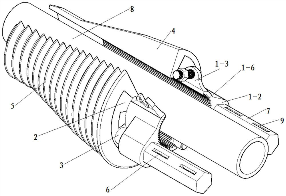
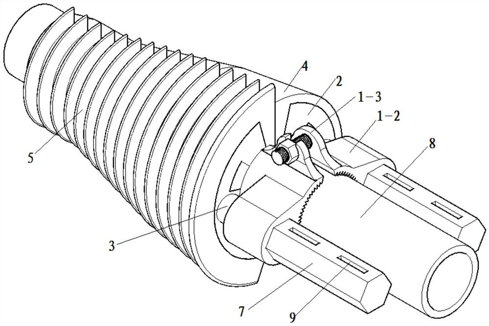
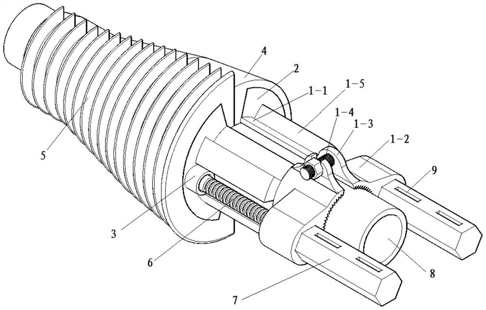
[0028] Such as Figure 1 to Figure 5As shown, the present invention includes a force-holding fixture clamped at one end of the leading small conduit 8 protruding from the palm surface, a sliding mold sleeve sleeved on the outside of the force-holding fixture and slidingly fitted with the force-holding fixture, and wrapped in the force-holding fixture. The elastic stopper on the outside of the sliding die sleeve and used to block the gap between the leading small conduit and the hole wall, the holding force clamp includes two matching holding force clamps, and the holding force clamp includes Splint 1-1, guide ear plate 1-2 installed on the end of holding force splint 1-1 away from the palm face and slideway 1-5 installed on holding force splint 1-1, guide ear plate 1-2 and sliding There is a gap between the lanes 1-5, and threaded holes 1-7 are provided on the guide ear plate 1-2. The sliding mold cover includes two matching sliding mold frames 2, and the sliding mold frame 2 ...


PUM


Abstract

The invention discloses an energy-saving tunnel leading small conduit quick-installation and slurry-stopping structure, which includes a force-holding fixture clamped at one end of the leading small conduit protruding from the palm surface, sleeved on the outside of the force-holding fixture and slidingly matched with the force-holding fixture The sliding die sleeve and the elastic stopper wrapped on the outside of the sliding die sleeve and used to block the gap between the leading small conduit and the hole wall, the rotating thrust sleeve pushes the sliding die sleeve and the elastic stopper to move synchronously through the push bolt. The present invention is firmly connected with the leading small conduit through the holding fixture, and provides a base for the positioning and pushing of the elastic stopper. Easy to operate, flexible and flexible, no need to wait for the concrete to solidify, shorten the process time, promote the construction cycle, improve the construction efficiency of the grouting construction personnel, reduce the waste of grouting materials and cost investment, improve the efficiency and effect of grouting construction, and solve the problem of strands of water in the borehole In severe cases, the packing cannot be formed.

Description

technical field [0001] The invention belongs to the technical field of fast installation and stoppage of a small leading conduit, and in particular relates to an energy-saving structure for quick installation and stoppage of a small leading conduit in a tunnel. Background technique [0002] The tunnel site is constructed in a plateau area with an altitude of more than 3,500 meters. The construction area has high altitude, harsh climate, and high environmental protection requirements. The oxygen content and air pressure value are only 65% ​​of the normal value. The ventilation length of the long tunnel in the plateau alpine area is long, and affected by the environment of low pressure and low oxygen content, the efficiency of construction equipment and personnel efficiency are seriously reduced. Energy saving control is particularly important in tunnel advance small conduit grouting construction. [0003] Usually the tunnel is constructed with a small conduit in advance, and...

Claims


Application Information

Patent Timeline
Patent Type & Authority Patents(China)
IPC IPC(8): E21B33/12E21D11/10E21D9/00
CPCE21B33/12E21D11/10E21D9/001
Inventor 姚志军姚庚辰李文纲骆铁林张少兵赵波陈迪王朋鹏孔任祥
Owner CHINA RAILWAY FIRST GRP CO LTD
Why Eureka
Try Eureka