
Dual-vertical polarization artificial dielectric cylinderical multi-beam antenna

A multi-beam antenna and artificial medium technology, which is applied to antenna unit combinations, antennas, antenna arrays and other directions with different polarization directions, can solve the problems of complex antenna structure, large area and high energy consumption, and achieve the effect of improving the gain.

Active Publication Date: 2020-11-06
XIAN HAITIAN ANTENNA TECH CO LTD
View PDF9 Cites 6 Cited by
  • Summary
  • Abstract
  • Description
  • Claims
  • Application Information

AI Technical Summary

Problems solved by technology

[0007] In order to solve the technical problem that the antenna gain and the vertical plane radiation range commonly existed in mobile communication base stations in the prior art cannot be achieved at the same time, and the antenna structure is complex, the floor area is large, and the energy consumption is high, the present invention proposes an artificial medium-based Vertically polarized dual-stream multi-beam antenna with cylindrical lens, the specific technical scheme is as follows:

Method used


Image

  • Dual-vertical polarization artificial dielectric cylinderical multi-beam antenna
  • Dual-vertical polarization artificial dielectric cylinderical multi-beam antenna
  • Dual-vertical polarization artificial dielectric cylinderical multi-beam antenna

Examples


Embodiment 1

[0058] Such as Figures 6a-6d As shown, the dual vertical collinear (cylindrical lens and antenna unit) dual-stream four-beam antenna provided in this embodiment includes four cylindrical lenses 5 and four antenna units. Among them, the artificial dielectric cylindrical lens 5 is selected. The dielectric cylindrical lens 1 includes 11 concentric layers with different dielectric constants. The central cylindrical layer is represented as the first layer. The layers are assembled into a multilayer cylinder, and the dielectric constant of multiple concentric layers of the artificial dielectric multilayer cylindrical lens 5 decreases layer by layer from the first layer to the outside, from about 2.05 to 1.05. In the present invention, polystyrene is usually selected as the base material with low dielectric constant for manufacturing the cylindrical lens 5 , and the additive material with high dielectric constant is metal wire. The artificial medium cylinder 5 used in this embodime...

Embodiment 2

[0062] Such as Figures 9a-9d As shown, the difference between this embodiment and Embodiment 1 is that four single-stream antennas are added, and the newly added four single-stream antennas are vertically overlapped with the four single-stream antennas in Embodiment 1, and the eight single-stream antennas It includes eight antenna elements and eight cylindrical lenses 5 . Rotate the positions of the antenna units at positions 1, 2, 3, and 4 horizontally to the left by 30 degrees, and the positions of the antenna units at positions 5, 6, 7, and 8 to the right by 30 degrees horizontally, and the eight cylindrical lenses 5 The position is unchanged. After rotation, the horizontal and vertical directions of the antenna units are collinear, and the angle between the above two groups of antenna units is 60 degrees.

[0063] Figure 10 Shown is the horizontal plane pattern of the second embodiment provided by this embodiment (only the cylindrical lens collinear dual-stream eight-...

Embodiment 3

[0065] See attached Figure 5 As shown, the only difference between this embodiment and embodiment 1 is that n is 5.

[0066] The following uses Huawei's traditional 1.3*0.3m plate antenna as an example to compare with the technical solution provided in this embodiment. Its measured gain is 20dBi. Attached to the invention Figure 5 The measured gain of the provided dual-stream and dual-beam antenna can reach 15.3dBi.

[0067] From the perspective of "antenna caliber", Huawei's plate antenna and the attachment of the present invention Figure 5 Antennas are calculated separately:

[0068] The relationship between the directional coefficient D of the maximum radiation direction of a directional antenna and the aperture area is as follows

[0069] D=4π*(Ae / λ 2 ),

[0070] Antenna aperture efficiency η=log -1 ((G measured-D) / 10).

[0071] First calculate Huawei's high-speed rail ESC antenna:

[0072]Gain G(dBi)=20dBi, aperture size 1.3mx0.3m, frequency 1880MHz (waveleng...


PUM


Abstract

The invention provides a dual-vertical-polarization artificial dielectric cylindrical multi-beam antenna, which belongs to the field of base station antennas and comprises a cylindrical lens and an antenna unit, and is characterized in that the cylindrical lens is made of an artificial dielectric material and comprises a plurality of concentric layers with different dielectric constants; the antenna unit comprises a vertical polarization dipole antenna and a metal bottom plate, the vertical polarization dipole antenna comprises a vertical polarization dipole, and the vertical polarization dipole is fixed on the metal bottom plate; the antenna unit is arranged in the middle of the cylindrical surface of the cylindrical lens, and the polarization direction of the vertical polarization dipoleis parallel to the axial direction of the cylindrical lens to form a uniflow antenna; the multi-beam antenna comprises n single-flow antennas which are vertically arranged to form a double-flow n-beam antenna. The n vertically-arranged single-flow antennas are not in contact with each other; n is an exponential multiple of 2. The antenna has good innovativeness, and can still keep large-area radiation in the vertical direction and keep high gain on the basis of meeting the double-flow mode requirement of mobile communication.

Description

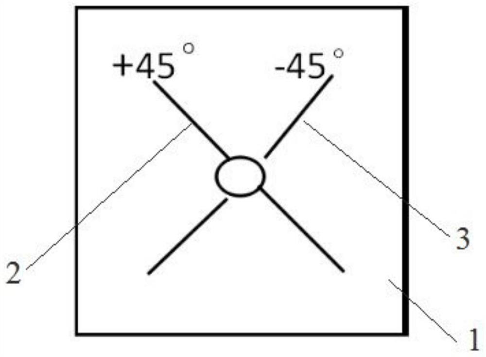
technical field [0001] The invention relates to the field of base station antennas, in particular to a dual vertically polarized artificial dielectric cylindrical multi-beam antenna. Background technique [0002] Traditional solution: Traditional mobile communication base station antennas, including plate antennas and various lens antennas, are composed of almost + / -45° dual-polarized half-wavelength dipoles. As attached in Chinese patent document CN 105659434 A image 3 As shown in a-3c, the phase centers of the two dipoles overlap. The two half-wave dipoles have the same and overlapping radiation field distribution in space, and the coverage and distance are exactly the same. Compared with two dipoles separated, the field strength of the field point is doubled, but it will bring disadvantages such as limited coverage. Technical personnel in the industry know that the usual method for increasing the gain of base station antennas is to increase the antenna unit, but every ...

Claims


Application Information

Patent Timeline
Patent Type & Authority Applications(China)
IPC IPC(8): H01Q19/06H01Q21/06H01Q21/24
CPCH01Q19/06H01Q21/06H01Q21/245
Inventor 王建青廖康焦西斌任玉文
Owner XIAN HAITIAN ANTENNA TECH CO LTD
Learn More